
Dock Electrical Safety: Where the Fault Loop Closes — and What the Structure Can Prevent
Where the Loop Closes: Why Water Turns a Small Fault Into a Fatal One
The framework here is the United States one. NEC Article 555 covers docking facilities; Article 682, natural and artificially made bodies of water; NFPA 303, marinas and boatyards; and ABYC E-11, the boat side, a voluntary consensus standard with force of law only where adopted. On BS 7671, AS/NZS 3000 or IEC 60364 outside the US, these clause numbers describe how one country solved the problem, not your local requirement. Not warehouse loading docks: this is the loop at the water’s edge.
A dock fault is rarely dramatic: an insulation failure, a corroded connection, a splice that has been taking on water since the season it was made. What makes it lethal is not contact but participation. Current leaves its source, finds a path through the water, and returns. Put a swimmer in that water and the swimmer becomes one of several parallel paths back, with the current dividing according to resistance. How much takes the body instead of the water is the entire question.
Where the Loop Closes Through a Swimmer
Four steps, no device anywhere in the path.
That division is why “freshwater is the dangerous kind” is a threshold shift, not a switch. Freshwater conducts poorly, so a body, which is largely salt water, is the better path and takes a disproportionate share; saltwater shunts most of the current around the body. A Coast Guard-funded study of marina electrical conditions found that leakage below 100 mA from a single vessel in freshwater was not a hazard to a person immersed nearby. In saltwater the danger threshold was around 500 mA. Five times the current, not immunity. A 2020 study in IEEE Transactions on Industry Applications reached the same place from the other direction: shunting is real and varies with conductivity, but risk does not vanish as salinity rises.
Do not swim within the electrical field of a dock, and do not enter the water to pull someone out. A rescuer who grabs a swimmer inside a live field becomes part of the same loop, which is why these incidents so often involve two people rather than one. Kill the power at the source first, or reach from a boat or the shore.
Saltwater is not safe; it is less favourable to the body per unit of leakage, and in exchange the dangerous zone is larger. What the numbers give you is a criterion for any water you stand beside: what is its conductivity, and how much current could be in it.
Where the Leak Forms Before Anyone Can See It
Four places a fault can be born: dock-side wiring and the runs leaving shore; underwater splices, where a connection sits permanently wet; the shore cord and the boat’s inlet; and the boat’s own systems, outside the dock’s boundary but not outside the loop.
The forms are ordinary; the timing is not. Electrical deterioration has no visible precursor, which is why a visual survey cannot substitute for measurement. NFPA’s own summary is that the general public will not see the hazard with their eyes and that failure typically occurs over time. One real inspection found a three-conductor cable with only one ungrounded conductor run out and jumped across to another terminal. A jumper had burned past recognition, and fourteen receptacles fed from a single 15-ampere breaker. All of it looked normal to anyone walking the dock. That is also why the wiring rules take the form they do: conduit, sealed entries, wet-location-listed equipment and UV-rated fittings remove the standing water and sunlight that turn a slow internal failure into an exposed one. Any check based on looking is the wrong instrument here; how often a dock should be inspected belongs to the companion article on dock inspection.
Three height figures circulate, and none is a receptacle rule. The NEC figure is 12 inches: components and connections at least that far above the deck, and the same minimum for replacement connections on a floating pier. That figure also sets a datum plane no lower than 12 inches above the deck and 30 inches above the water. The 36-inch figure is the horizontal reach of a 2023 equipotential plane or a local amendment; the 42-inch figure is the bottom of a disconnecting-means enclosure under local and utility rules. Neither is in Article 555, whose one dimension, 555.36, is proximity: the disconnecting means sits within 30 inches of the receptacle it controls.
What You Can and Cannot See from the Dock
The second list is the one that matters.
What you cannot do yourself is measure insulation resistance, inspect a submerged run, or verify that a bonding path is still continuous. Those need a licensed electrician and an instrument, not a DIY attempt. And know what a GFCI test button proves: that the device can still trip, not that the wiring behind it is intact. Pressing the button simulates a fault internally and never touches the protected circuit, so a dock can show a healthy indicator on every device and a failing conductor between them.
Three Sources, One Loop: Your Dock, the Boat, and the Grid
The dock side: the loop closes through your own distribution and underwater runs
The case everyone prepares for, and the easiest to reason about because the evidence is on your own property: damaged feeder insulation, a splice housing full of water, a receptacle wet since the last flood. This is the one failure mode where killing the dock’s power removes the source.
The boat side: the fault that is not yours
A 14-year-old died of electrocution drowning caused by a boat’s bad shore power connection. The account of that death drew a conclusion that was not about the dock at all: it wasn’t the dock, but the boat itself. The dock was functioning, the fault was on the vessel plugged into it, and the water did not care which side of the pedestal the current started on. Code commentary says the same from the other end: in many cases, the water’s voltage source is not the electrical distribution system. Shutting off the dock removes one source; it does not certify the water is clear.
The grid side: the waterway as a parallel return path
A waterway can act as a parallel return path for the utility’s distribution system, whose neutral is grounded to earth at multiple locations. Current belonging to the grid can travel through the water and back to the grid without passing through any dock equipment, so it passes through no GFCI and no GFPE on that dock. Nothing on your pedestals detects it, because from your installation’s point of view nothing is wrong. It also explains why the dock next door is part of your risk picture.
| Position | Current path | Who interrupts it | Checkable action |
|---|---|---|---|
| Dock side | Through the facility’s own distribution and underwater runs, back via the grounded system | The dock’s own GFPE or GFCI, if one is installed on that segment and functioning | Kill the dock supply and confirm the water clears. If it does not, the source is not yours. |
| Boat side | From the vessel’s shore power connection through the water, back to the source | Nothing on the dock — the dock’s devices see a healthy circuit | Disconnect the suspect vessel and re-measure. Test the boat, not the pedestal. |
| Grid (multi-grounded neutral) | Through the water as a parallel return for the utility’s distribution system | Nothing on your property at all | If the water carries current with your dock de-energised, escalate to the utility rather than your own contractor. |
Water with electricity in it does not mean your dock is leaking.
The point of separating the three is not to assign blame: attribution determines which segment you install a device on, which is the next question.
Three Closure Points, One Diagram
One figure, three positions — this is the image to keep.
Segmenting the Loop: Three Protection Levels and Four Conflicting Answers
Three levels, one diagram: 4–6 mA, 30 mA, 100 mA
The three thresholds are the most repeated numbers in this subject and the least safely repeated, because the clause containing them has moved. In the 2020 NEC they sat in 555.35(A)(1), (A)(2) and (A)(3); 2023 reorganised the same thresholds into 555.35(A) for feeders, 555.35(B)(1) for shore power branch circuits and 555.35(B)(2) for other-than-shore-power outlets. The values did not change; the addresses did. Name the edition before you write one of these numbers into a specification.
| Loop segment | Gerät | Threshold (confirm against your adopted edition) | What it protects / what it does not |
|---|---|---|---|
| Service entrance facility feeder | GFPE | Not more than 100 mA — 2020 NEC 555.35(A)(3); 2023 NEC 555.35(A) | Reduces leakage current entering the water from the facility. Not a shock-protection threshold. |
| Berth branch shore power receptacle | GFPE | Not more than 30 mA — 2020 NEC 555.35(A)(1); 2023 NEC 555.35(B)(1) | The compromise level: reduces most ESD incidents while limiting nuisance tripping. Not listed as personnel protection. |
| Ordinary 15/20 A receptacle | Class A GFCI | Trips at 6 mA or more, must not trip at 4 mA or less — UL 943 | Genuine personnel protection — the only tier on this list that is. |
| Vessel side, where more than three receptacles supply shore power | Leakage current measurement device | No threshold; a measurement requirement — 2020 NEC 555.35(B); 2023 NEC 555.35(D) | Makes an individual vessel’s leakage measurable. It identifies the source; it does not interrupt it. |
Why four sources give three answers: term drift and version drift
Two mechanisms explain almost all of it. The first is term drift: sources collapse “branch circuit” and “receptacle” into one another, putting a 100 mA device where a 30 mA device belongs. Read any threshold claim and ask which segment the sentence is about, whatever word it used.
The second is version drift, more dangerous because a source can be internally consistent and still a decade out of date. For the 30 mA requirement, 555.3 was the old address, and material written against that numbering still circulates. The scope moved too. Article 555 was amended in 2017 to reach docking facilities at one-family, two-family and multifamily dwellings and residential condominiums. The claim that it does not reach a private residential dock has therefore been wrong for several editions. The 2023 reorganisation added 555.15 for replacing existing marina electrical equipment and 555.14 for equipotential planes and bonding. None of that argues for distrusting the sources; it argues for dating them. How the numbers moved is this section’s subject; whose code governs your job, and who must sign off on it, belong to the companion article on dock inspection.
Protection is not a solution: the sensitivity-vs-availability trade-off
The most important threshold on that table is the one that is not on it. A device set at 100 mA does not protect people. The code panel that produced the marina requirements recorded that the 100 mA level recommended by Coast Guard research was far above the Class A range and would not prevent the muscle tetanisation of children in the water. NFPA’s summary says the same: GFPE and GFCI protection alone does not solve the problem.
Sensitivity buys something you did not ask for. One British Columbia account describes Class A GFCI tripping on winter bilge pumps, and the trade monitoring each receptacle with indicator lights. The reason, in the poster’s words: boaters get irate when the yacht sinks under the sea. A retrofit elsewhere tripped an entire feeder and took every neighbouring berth down with it. Fifteen boats at rest in a freshwater marina, all on shore power, averaged 3.9 mA of leakage each, ranging from 0.0 to 15.5 mA. Across twenty-four outlets on one dock, that reaches 72 mA at the feeder and 360 mA at the main before anything is wrong.
So before you set a threshold, three things to check rather than assume. Establish what on that loop cannot lose power (a winter bilge pump is the standard example) and set sensitivity around that, not around the number alone. Do not treat a higher threshold as the fix for nuisance tripping. And before reworking an older facility, confirm the loop can be re-segmented.
What the Structure Does to the Loop: Non-Conductive Hulls, Metal Fasteners, and Bonding
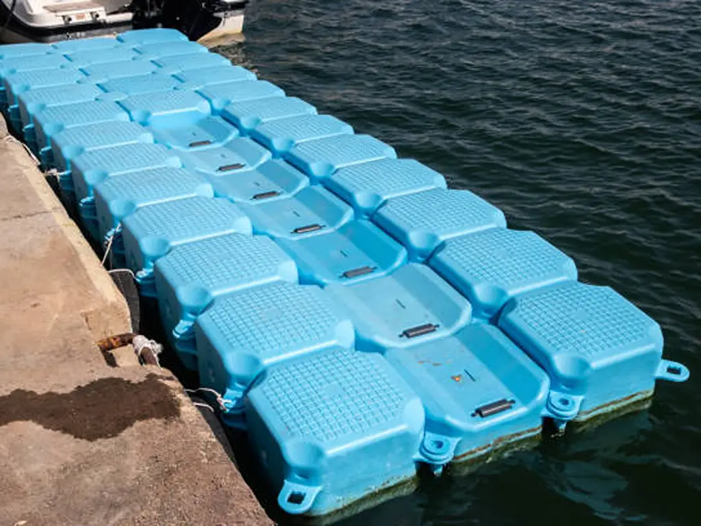
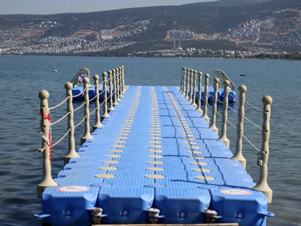
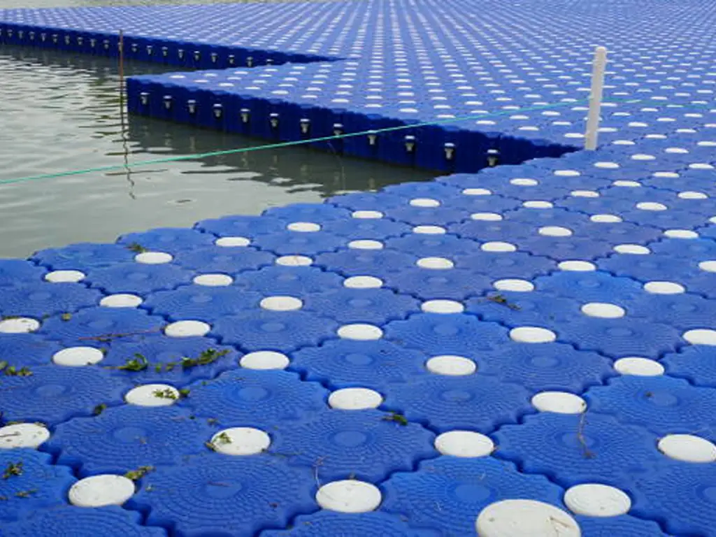
Your dock’s float is made of high-molecular-weight HDPE, a dielectric with very high volume resistivity. That consequence is narrow: the float body cannot become an energised conductor and cannot carry fault current. It is not a path.
It does not buy the inference everyone reaches for next. A non-conductive body has no bonding target, which is not the same as having no bonding requirement, because the structure is not only the float. Every metal part on it is still a conductive part in a wet environment: pins, bolts, washers, pile guides, rail posts. NEC 555.13 requires all metal parts in contact with the water, and all non-current-carrying metal parts likely to become energised, to be connected to the grounding bus in the panelboard, with a conductor not smaller than 8 AWG solid copper. On a non-conductive float that becomes a set of physical questions: where the metal parts are, whether a bonding conductor can reach them, and where it runs.
Modular construction adds a second problem: the connection points between sections, such as pins, long bolts and connection ears, are mechanical joints, and mechanically they are also the breaks in any bonding path. Continuity across a hinge point needs a bonding jumper, and that cannot be read off a drawing; it must be designed in.
Two facts keep the material story honest. A wet surface is not an insulating surface. Salt films, algae and fouling form contamination layers that conduct, so a plastic structure cannot be a fault path; that is not the same as nothing on it becoming energised. And equipotential planes are governed outside Article 555, in NEC 682.33, with a parallel requirement added for docking facilities in 2023. Whether one can be delivered depends on whether the structure left a location for it when it was moulded.
| Facility scale | What holds | Where the boundary is | Checkable action |
|---|---|---|---|
| Private single-berth residential dock | The float body is not a fault path; the loop cannot close through the structure itself | The metal on the structure is still on the loop — pins, bolts, washers, rail posts, ladder and lift hardware | Walk the dock and list every metal part that touches water or could be energised. Ask who bonds them, and to what. |
| Multi-berth commercial marina | Segmentation is meaningful because each berth’s leakage accumulates upstream | The feeder sees the sum of every berth, so one vessel’s fault can open a device protecting the whole dock | Have per-berth leakage measured before setting feeder thresholds, and confirm the loop can actually be re-segmented. |
| Resort or marina with a designated swim area | A posted boundary and a de-energisation procedure are enforceable rules | Equipotential bonding depends on the structure and on pile positions; it is not retrofittable at will | Establish whether an equipotential plane is feasible at the swim boundary before the structure is specified — not after. |
“Non-conductive” never licenses the jump to no grounding, no bonding, no risk. The float is off the loop; the hardware on it is not.
Buying the Provision, Not the Repair: What Has to Be Fixed at the Structural Stage
At facility scale, one fault is everyone’s fault
The two failure accounts above are one lesson told twice: the retrofit that took every neighbouring berth offline, and the Class A installation that put boats on the bottom. Neither was a device that failed: both were protection decisions taken without regard to what the loop had to keep doing, and the cost was not borne by the berth where the fault was.
Four things to write into the structural specification
Which is why the decision that matters comes earlier than almost anyone treats it. Protection devices can be added or replaced on any day of a dock’s life; the things that determine whether they can be added, reached and maintained are set when the structure is made. ① A continuous cable route: pre-formed, sized grooves or channels, so a conductor runs protected rather than surface-clipped. ② Reserved holes and mounting faces at defined, indexed locations for posts, pedestals, panel and signage. ③ Bonding reachability and continuity for the metal parts, and whether continuity survives the joints between sections. ④ The physical location of the loop segmentation: where the shore power receptacles and the branch-circuit device will actually sit.
Three quotes for three floating docks that look identical will not be quotes for the same product on these four items, and the quote will usually say nothing about any of them. That is the one category of cost on a dock project that cannot be priced, compared or corrected once the piles are in. Where the project is already built, three of the four are usually gone. And if a supplier cannot say where the cable route runs or where the mounting points are, ask for the reserved hole positions rather than whether the dock “supports cabling”.
To be plain about the line: we don’t sell electrical equipment, we don’t install or inspect dock wiring, and we can’t tell you which rules apply to your site or what your inspector will accept. That call belongs to your licensed electrical engineer or your local authority having jurisdiction — not to us.
Where this topic meets our work is the structure the wiring has to live in. Pre-formed grooves, reserved pin and bolt holes, and fixed mounting points for posts and pile guides are set when the floats are molded, not three years later — and the Pipelined Float is the one in the Hisea Dock range with a route formed in for water pipe and power cable. If that is relevant to a dock you are planning or specifying, get in touch and we will talk through the layout and the structure underneath it.
Plan the cable route before the dock is built
Tell us where power, water lines and mounting points need to sit. We will help you review the float layout and cable-routing options before the structure is fixed.
References
- National Fire Protection Association. “Protect Yourself from Electric Shock Drowning.” https://www.nfpa.org/education-and-research/electrical/electric-shock-drowning
- IAEI Magazine. “History of Marina Ground-Fault Protection.” https://iaeimagazine.org/electrical-safety/history-of-marina-ground-fault-protection/
- Electrical License Renewal. “555.35 Ground-Fault Protection of Equipment (GFPE) and Ground-Fault Circuit-Interrupter Protection.” https://www.electricallicenserenewal.com/Electrical-Continuing-Education-Courses/NEC-Content.php?sectionID=1531
- UpCodes. “Ground-Fault Protection of Equipment (GFPE) and Ground-Fault Circuit-Interrupter Protection.” https://up.codes/s/ground-fault-protection-of-equipment-gfpe-and-ground-fault-circuit-interrupter
- Washington State Legislature. “WAC 296-46B-555 Marinas and Boatyards.” https://app.leg.wa.gov/wac/default.aspx?cite=296-46B-555
- ANSI/ABYC. “E-11-2025, AC and DC Electrical Systems on Boats.” https://webstore.ansi.org/standards/abyc/abyc112025
- National Fire Protection Association. “NFPA 303, Fire Protection Standard for Marinas and Boatyards.” https://www.nfpa.org/product/nfpa-303-standard/p0303code
- EC&M. “The Case of Stray Voltage in a Lake.” https://www.ecmweb.com/power-quality-reliability/article/20898273/the-case-of-stray-voltage-in-a-lake
- Mike Holt. “Marina GFP Concerns.” https://www.mikeholt.com/newsletters.php?action=display&letterID=1772
- Mike Holt. “Marina Leakage Measurement Device.” https://www.mikeholt.com/newsletters.php?action=display&letterID=2019
- Electrical Safety Foundation International. “Boating and Marina Safety Brochure.” https://www.esfi.org/boating-and-marina-safety-brochure/
- NSS Ltd. “2026 Code Year: NEC 555.” https://www.nssltd.com/posts/2026-code-year-nec-555
- Mike Holt. “Remove Electric Shock Drowning Hazard at Residential Docks.” https://www.mikeholt.com/files/PDF/Proposal-Remove_Electric_Shock_Drowning_Hazard_at_Residential_Docks.pdf
- University of Arkansas ScholarWorks. “Modification of Surface Properties of Polymeric Materials.” https://scholarworks.uark.edu/jaas/vol56/iss1/24/
- Mike Holt Forum. “Inspecting Boat Docks.” https://forums.mikeholt.com/threads/inspecting-boat-docks.41352
- Electrician Talk. “Boat Dock Inspection.” https://www.electriciantalk.com/threads/boat-dock-inspection.233402/
- Hisea Dock. “Pipelined Float.” https://www.hiseadock.com/product-item/pipelined-float/
- Hisea Dock. “Dock Accessories.” https://www.hiseadock.com/dock-accessories/

 English
  Thai
Thai  Spanish
  French
  German
  Dutch
Dutch  Italian