
Best Floating Dock Systems: The Five Envelopes That Decide Which One Is Actually Best
Search for the best floating dock systems and you will get two kinds of answers. One is a brand list. The other is a material comparison that ends with “it depends.” Neither tells you what you actually need, which is a way to judge a system against your own water, your own traffic, and your own books.
Here is the framework this article uses. Every floating dock system, whatever it is made of and whoever builds it, has to hold up at five separate points: buoyancy, load path, connections, compliance, and supply. They are independent. A system can be excellent at four of them and fail at the fifth, and the fifth is the one that ends the project.
Material names do not predict which envelope fails. That is why a ranked list cannot answer your question.
The five envelopes, and the question each one answers
What Counts as a Floating Dock System
The word “dock” covers two unrelated products in the same search results.
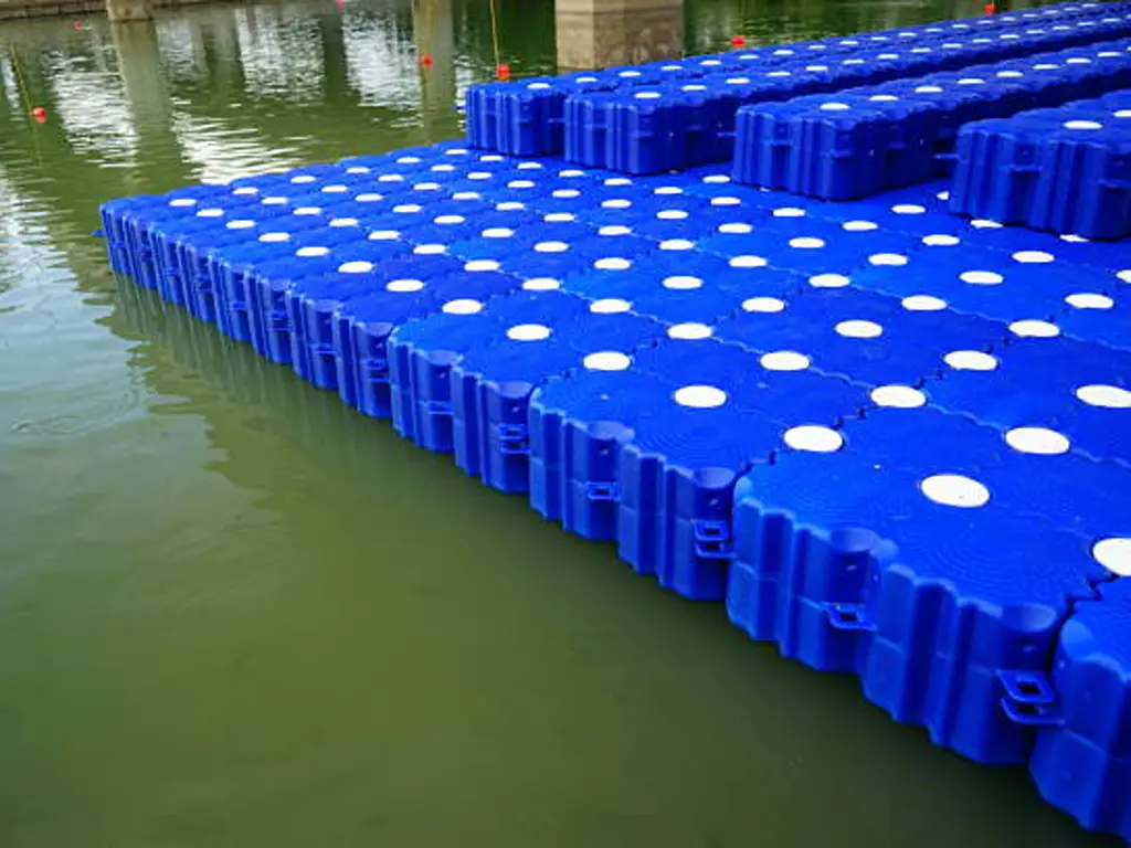
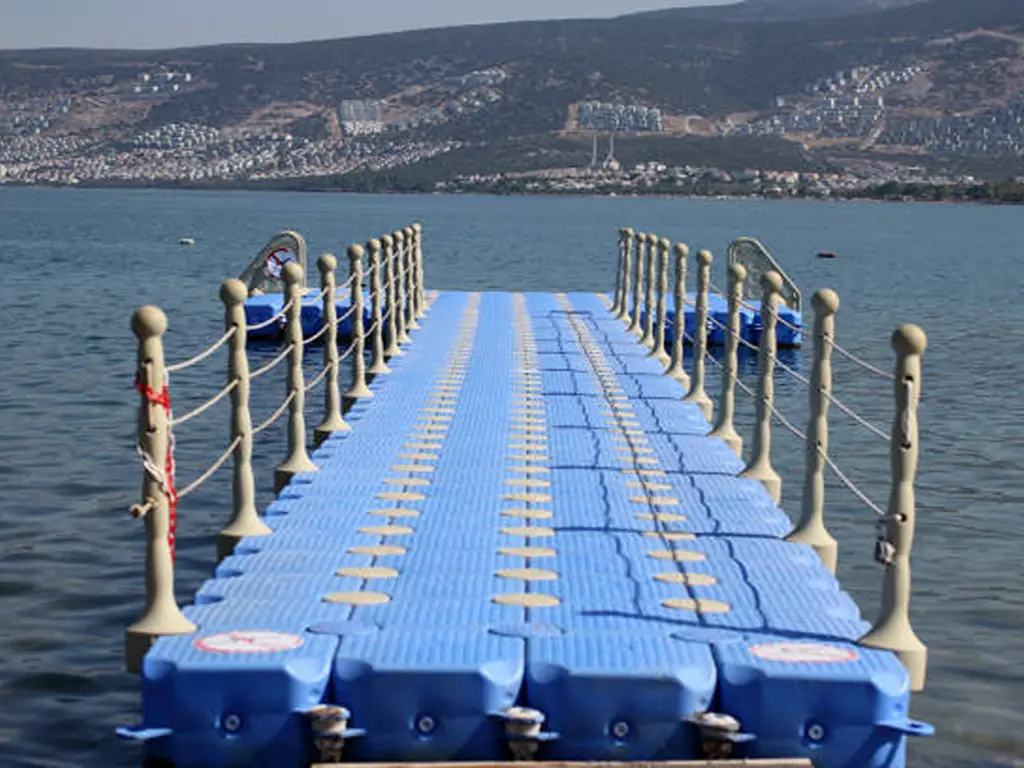
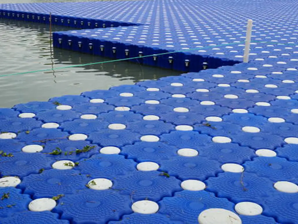
เอ ระบบท่าเทียบเรือลอยน้ำแบบแยกส่วน is a platform that stays in the water, is anchored in place, and carries people and boats across seasons. A floating swim dock is an inflatable mat, usually drop-stitch PVC, that you blow up at the boat and roll up afterward.
The dividing question is not size or price. Ask it this way: does it need to be anchored, and can you fold it into a boat locker?
Which of these are you actually shopping for?
If it needs anchoring and will not fold, it is a system, and the rest of this article applies. If it folds, it is recreation equipment.
One more boundary worth setting early. Floating against fixed is a separate decision from this one. Floating wins where water levels move; fixed wins on stable, shallow shorelines. Settle that question first, because the criteria below only sort among floating options.
Envelope One — Buoyancy: How Much It Lifts, and in Which Units
Buoyancy is a function of displaced volume, not of material. A hollow chamber lifts whatever weight of water its volume displaces, and any material can enclose that chamber. This matters because the spec sheet usually states the figure in one of two units, and buyers routinely compare across them as if they were the same.
Area load is measured in kilograms per square meter and describes how much a deck area floats. Per-unit load describes how much a single cube holds. Take a common 500 × 500 × 400 mm cube rated at 350 kg/m². Its footprint is 0.25 m², so it floats 87.5 kg, which is the same figure a supplier would publish as roughly 90 kg, or 200 lbs, per cube.
Both numbers are correct. They describe the same cube. Only one of them answers the question you asked.
One cube, two units
500 × 500 mm gives a 0.25 m² footprint. 350 kg/m² × 0.25 = 87.5 kg. Same cube, two units, and neither figure is wrong.
What the construction of the chamber changes is not capacity but whether a failure can be undone. A sealed hollow chamber that cracks loses its displacement permanently. The cavity floods and stays flooded. A foam core inside a shell absorbs water slowly and degrades over years rather than in one event. An inflatable loses buoyancy the moment it deflates, and regains it the moment it is re-inflated. None of these is universally better. They fail on different clocks.
Freeboard and draft belong to the same trade-off. A low-profile cube around 250 mm high sits close to the water, which makes it easier to board from a kayak, cheaper to ship, and less load-bearing per footprint. A 400 or 500 mm cube lifts more and stands further off the water. A draft of 2 to 4 inches is typical at the low end of that range.
Sufficient buoyancy does not make a system sound. It only means the platform floats.
How each chamber construction fails
Envelope Two — Load Path: Where the Force Actually Goes
Distributed Load and Concentrated Load Are Two Different Accounts
A load rating describes a distributed load: people standing across a deck. A dock also takes concentrated loads at a handful of points, which is what a cleat or bollard, a handrail post, a boarding step, the entry to a U-shaped slip, or a roller for a personal watercraft all produce. Those forces arrive at one location, not across an area.
No conversion exists between the two. A floor rating cannot be divided into a point rating, because the two describe different mechanisms. One is about total displacement. The other is about how much stress a small area of structure and its fasteners will accept. A supplier who gives you only one has answered half your question.
The split matters more in commercial work than most buyers expect. Marine mooring hardware is rated by failure load, and the standard practice is to design the fitting so that the holding-down bolts fail before the structure does, making the connection point deliberately sacrificial so that overload damages a replaceable part instead of the platform. That logic exists because concentrated loads are the ones that take docks apart.
Load Types and Where to Check Them
| Load type | How it arrives | What carries it first | What to confirm |
|---|---|---|---|
| Distributed (people standing) | Spread across deck area | The buoyancy chamber’s displacement | Area rating in kg/m², and the footprint it assumes |
| Concentrated (cleat, rail post, boarding step) | At one fitting or edge location | The fasteners and the plate they pass through | A per-point rating, or written confirmation that none is published |
| Dynamic (boat contact, roller entry, fender compression) | Repeated impact rather than a static push | Edge geometry and flexible elements | Whether impact is absorbed by a replaceable part |
| Eccentric (crowd to one side) | Offset from the platform centre | Footprint, and connection stiffness across the array | Whether a larger footprint is needed for your use |
Eccentric Load and Why Footprint Matters
Load that sits off-centre tilts the platform before it overloads it. A group gathered on one edge, or a boarding point on a corner, shifts the centre of gravity and puts unequal demand across the connections. The fix is usually geometric rather than structural, since a larger footprint spreads the offset across more cubes.
This is why the same rating supports more people on a wide platform than a narrow one, and why copying a neighbour’s configuration can disappoint even when both systems carry the same rating.
An area rating is not a per-point rating, and nothing converts one into the other. Using “350 kg/m²” to justify a cleat, a rail post, or a boarding step load is the single most common spec-sheet misread in this category, and it is the one that produces warranty claims.
Envelope Three — Connections: What Decides How Long It Lasts
Why Published Lifespans Disagree
Published service lives for floating docks run from a couple of years to five decades. The spread is not mainly a materials argument. It is a measurement argument, in which different numbers describe different things, and some describe a component rather than a structure.
A coating that needs recoating every five to seven years is not a dock with a five-year life. A structure rated over 40 years has not been tested for 40 years. And a connector that fails at year twelve ends the system’s life regardless of how well the deck is holding up.
The most consistent engineering finding here is blunt: the connections between modules are the weakest components of a modular floating structure. Work on modular floating breakwaters and multi-body platform arrays identifies two failure modes, rupture under extreme load and material fatigue under ordinary cyclic loading across the service life. Fatigue is the one that gets missed, because nothing looks wrong until it does.
What the Analysis Misses at the Connection
A 2025 study in the Journal of Ocean Engineering and Technology on a floating multi-body connector makes the gap concrete. A standard global beam analysis of the structure predicted a connector fatigue life of 30 to 1,533 years. Adding local shell modelling to capture stress concentration at the fixed connection points dropped the corrected estimate to 1 to 47 years, against a 25-year design life. Past roughly 5% extreme-wave probability, the beam-only method still returned a pass while the corrected method returned a fail.
Read that as a buyer rather than an engineer. The published fatigue figure for a connection depends heavily on how conservatively it was calculated, and the optimistic method is the common one. That is not a reason to distrust the product. It is a reason to ask what was analysed.
How Connection Types Distribute Margin
| Connection type | How force transfers | Where stress concentrates | What it is good at |
|---|---|---|---|
| Rigid pin or bolt fixing by corner position | Directly, section to section | At the fixed points and the plate around them | Holding an array in a fixed layout |
| Flexible coupling between sections | Through an elastic element that moves with the wave | Away from any single point | Dissipating wave energy instead of resisting it |
| Bolted plate with a sacrificial fitting | Into replaceable fasteners first | In the fasteners, by design | Protecting the main structure from overload |
| Over-sized lug thickness | As a larger section at the joint | Over a broader area at the joint | Storm margin, not carrying capacity |
What you can act on: connections take every wave, every tide, and every boarding as a cycle, and static load ratings do not describe cycles. Rigid connections transfer force directly and concentrate stress at fixed points. Flexible couplings let sections move independently and dissipate wave energy instead of resisting it. Neither is superior in the abstract, because they distribute margin differently. And a thicker connection lug buys storm margin, not carrying capacity. Those are two separate purchases, and sellers routinely let them blur together.
“The floats need to be replaced. You may get through the season if there is enough buoyancy. Have run marinas since 1988.”
Reply to a floating dock owner reporting cracks at the waterline — r/boating, 2024That thread is worth reading in full. The owner found water coming out of the hole he was trying to patch, because the cavity had already flooded. The reply from a long-time marina operator notes the second-order damage: missing plastic puts added stress on the sections that are still intact.
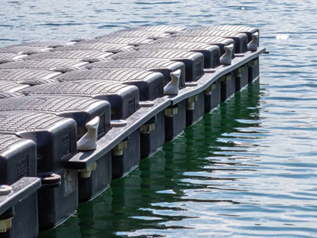
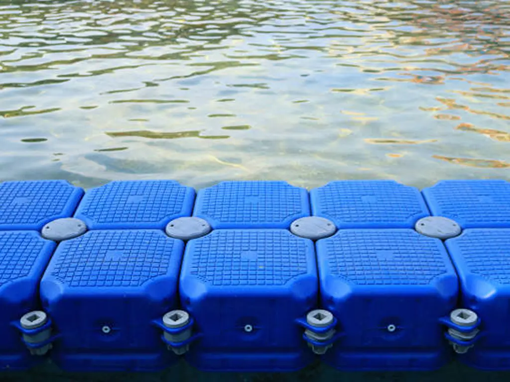
At Hisea Dock we publish the connection geometry rather than a single load figure. The lug runs 19 mm thick, and the reserved pin and bolt holes are indexed by corner position, so corners 1 and 4 take one fixing while corners 1,3 or 2,4 take another, with separate long pins and bolts for double-layer builds. The fixing pattern traces to a drawing instead of to the installer’s judgement. We also publish the diagonal tensile test result: a maximum force of 14,389 N, measured on the diagonal of the assembled cube. Ask every supplier you compare for the equivalent. What was tested, on which axis, and under what method? A connection figure without its test method is not a specification.
Envelope Four — Compliance, and Where Your Scenario Sits
Regulation has started to reach into the buoyancy chamber itself, and this is the envelope most buyers check last.
Effective 1 January 2024: polystyrene foam in overwater structures must be fully enclosed in a shell of plastic at least 0.15 in thick, or of concrete, aluminium, or steel. Civil penalty up to $10,000 per violation. Upgrades and repairs must comply, not just new installations.
The direction of travel is clear; the speed is not. California’s AB 2916 would have applied an identical framework, with the same 0.15-inch shell, the same $10,000 ceiling, and the same 2026 start, and it died in the Assembly Appropriations suspense file on 16 May 2024. New York’s S1129, which would bar polystyrene foam docks, buoys, and floating structures, has been referred and re-referred without a recorded vote. One state has enacted it. A second wrote the same law and did not pass it. A third is pending.
That is the useful form of the fact for anyone selling or specifying docks. Exposure is regional and legislative, not yet universal, and it moves between sessions. The practical consequence is that a system containing exposed or film-wrapped foam carries a compliance risk that a fully enclosed or foam-free system does not, and that risk lands on whoever sells or installs it rather than on the end user.
Where Each Scenario Hits Its First Limit
| Scenario | First envelope to bind | What you see when it does | What to confirm before deciding |
|---|---|---|---|
| Lake or pond, sheltered | การลอยตัว | Draft too deep, wet boarding, awkward step-on | Area rating, footprint, and the per-unit figure behind it |
| River with current | Connections | Fasteners working loose, array drifting off position | Anchoring method and the sustained load it carries |
| Water that freezes | Connections | Cube deformation, connector fatigue, sheared fixings | Overwintering plan: ride the ice, lift out, or de-ice |
| Public or semi-public site | Load path | Local sinking, rail and step fixings overstressed | Per-point ratings at rail, step and cleat locations |
| Commercial marina, multiple berths | Connections and compliance | Array separation, or foam that cannot legally be installed or repaired | The acceptance standard, and whether any foam is exposed |
| Industrial work platform | Compliance and supply | Permit delays, spares unavailable mid-project | Which agency has jurisdiction, and the spare and tooling list |
Envelope Five — Supply: What a Dealer Is Really Signing Up For
The first four envelopes live on the product. The fifth lives on the invoice, the warranty, and the shipping schedule, and it is the only one where you carry the residual risk rather than the product.
Four things decide whether it holds: whether spares are available, whether the tools arrive with the order, how a warranty claim is actually executed, and whether lead times hold in peak season. None of them appear on a specification sheet. All of them appear in what you signed.
That is the trade a dealer makes. A system with strong margins on the first four envelopes and no terms on the fifth hands the least controllable risk to the person who sold it.
Before you sign
Hisea Dock answers those four in the same order. Warranty is five years, with free replacement of damaged product within that period, stated on our homepage rather than buried in a terms page. Spares are a stocked line rather than a special order, covering pins, long bolts, screws, washers and cushions, plus the tools that go with them, including a dedicated spanner, mallet, and plug tool. Lead times run 7–10 days for production when stock is out, 10–15 days for custom builds, and most accessories ship within 10 working days. Where no local distributor covers your territory, we ship directly to the freight station your customer nominates.
None of that is unusual in itself. It is simply what the fifth envelope looks like when it is written down, and it is the list to hold every supplier you are comparing to.
Put your water, your traffic, and your books against the five envelopes. The one that binds first tells you what to check hardest. If you want to compare another supplier’s range against those five, tell us about your water and your traffic and we will answer the same questions we have just told you to ask.
Have your site assessed against all five envelopes
Send your water conditions, traffic, and season. We’ll return the cube layout, the load figures behind it, and the production window for your build.
Request a site assessmentReferences
- Washington State Legislature. “RCW 70A.245.130 — Overwater Structures Containing Certain Plastic Foam; Prohibition on Sale, Distribution, Installation.” https://app.leg.wa.gov/RCW/default.aspx?cite=70A.245.130
- Washington State Department of Ecology. “Foam Docks and Blocks Law.” https://www.ecology.wa.gov/waste-toxics/reducing-recycling-waste/plastics/docks-and-blocks
- CalMatters Digital Democracy. “AB 2916: Environmental Health: Floating Devices: Expanded Polystyrene (2023–2024).” https://calmatters.digitaldemocracy.org/bills/ca_202320240ab2916
- New York State Senate. “S1129 — Polystyrene Foam Docks, Buoys and Floating Structures (2025–2026 Session).” https://open.pluralpolicy.com/ny/bills/2025-2026/S1129/
- Journal of Ocean Engineering and Technology 39(3). “Time Domain Stress and Fatigue Life Evaluation for the Connector of a Floating Multi-Body in Waves by Total Beam and Local Shell Analyses.” https://joet.org/journal/view.php?number=3193
- Cebada Relea, A. “Structural Reliability Improvement of Modular Floating Dock Connections: Hydrodynamic Numerical Modelling, Extreme Load Analysis and Fatigue Assessment.” https://dialnet.unirioja.es/servlet/tesis?codigo=342516
- U.S. Department of Defense. “UFC 4-152-01 — Piers and Wharves.” https://www.wbdg.org/FFC/DOD/UFC/UFC_Complete_4-010-01_thru_4-159-03.pdf
- r/boating. “Floating Dock Cracks in Float.” https://www.reddit.com/r/boating/comments/1dfvken/floating_dock_cracks_in_float/
- Hisea Dock. “Plastic Floating Dock Systems Manufacturer.” https://www.hiseadock.com/
- Hisea Dock. “Products — Floating Dock Cubes and Accessories.” https://www.hiseadock.com/products/
- Hisea Dock. “Quality — Testing and Certifications.” https://www.hiseadock.com/quality/
- Hisea Dock. “Contact Us.” https://www.hiseadock.com/contact-us/

 English
  Thai
Thai  Spanish
  French
  German
  Dutch
Dutch  Italian