
You can install a grating deck over HDPE dock floats if the grating has a frame to bear on and the float manufacturer approves the frame’s bearing and attachment points. On a dock that already has a structural frame, start by checking beam spacing, connections and added weight. On an interlocking cube dock used as the walking surface, ask the manufacturer for a retrofit detail or a separately designed framed system.
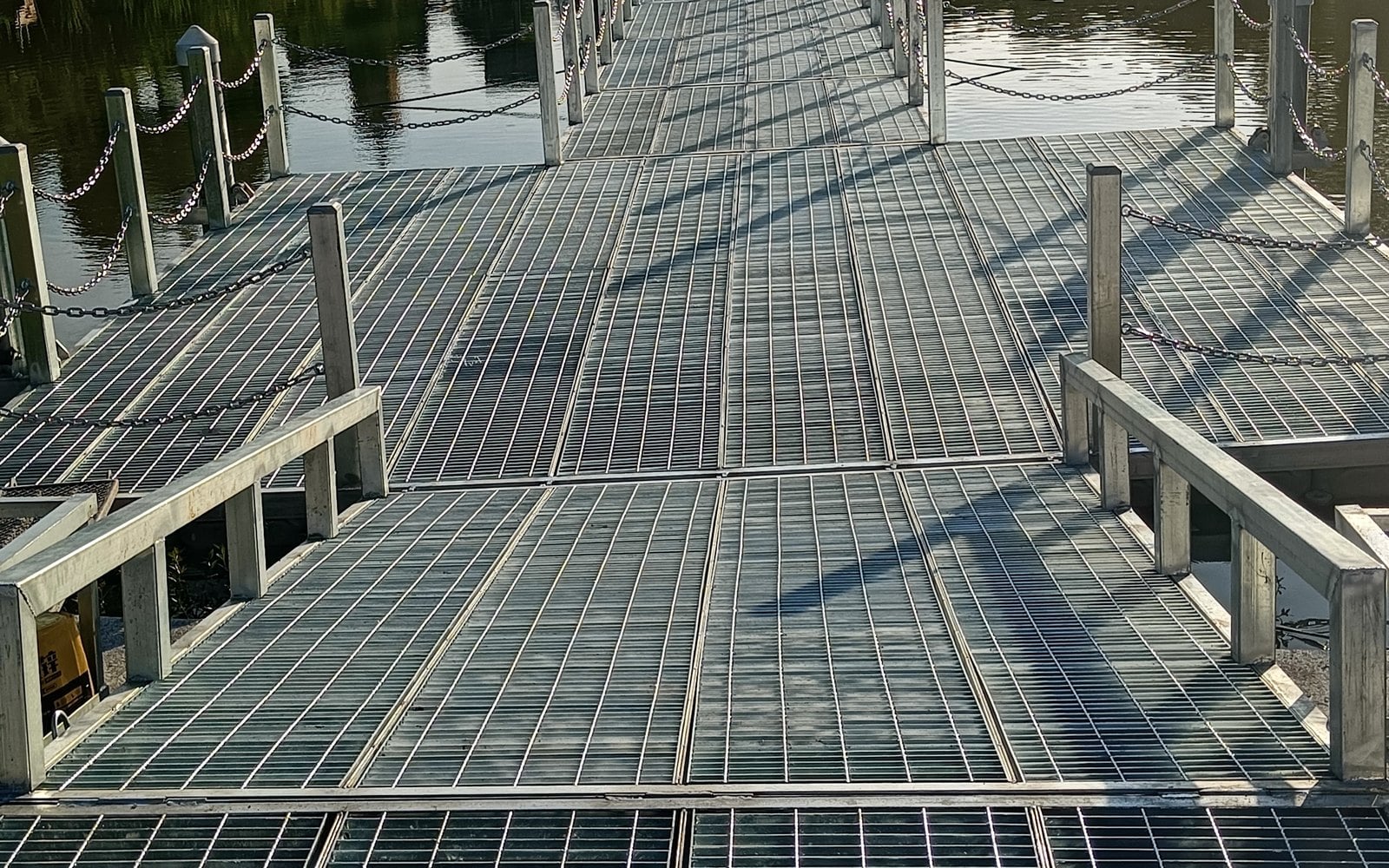
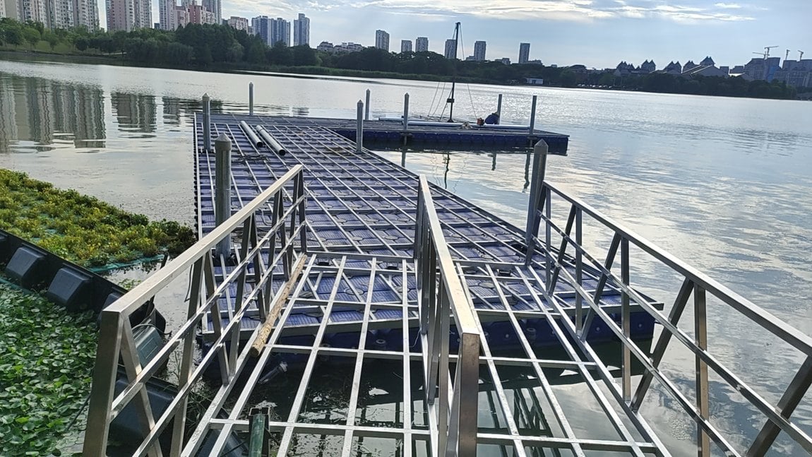
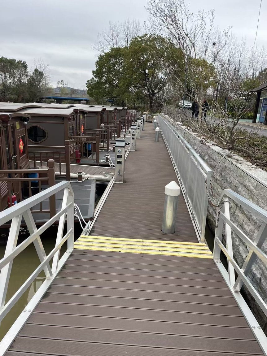
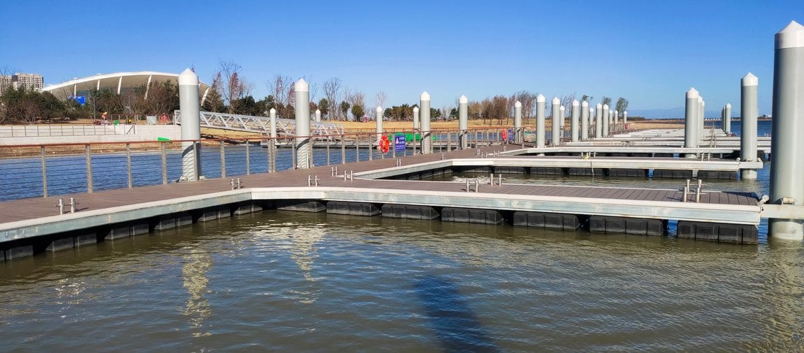
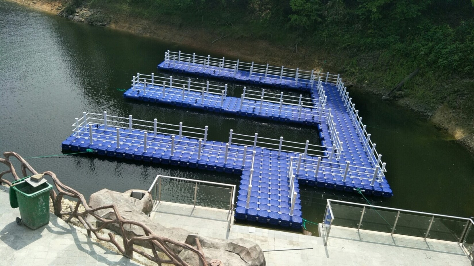
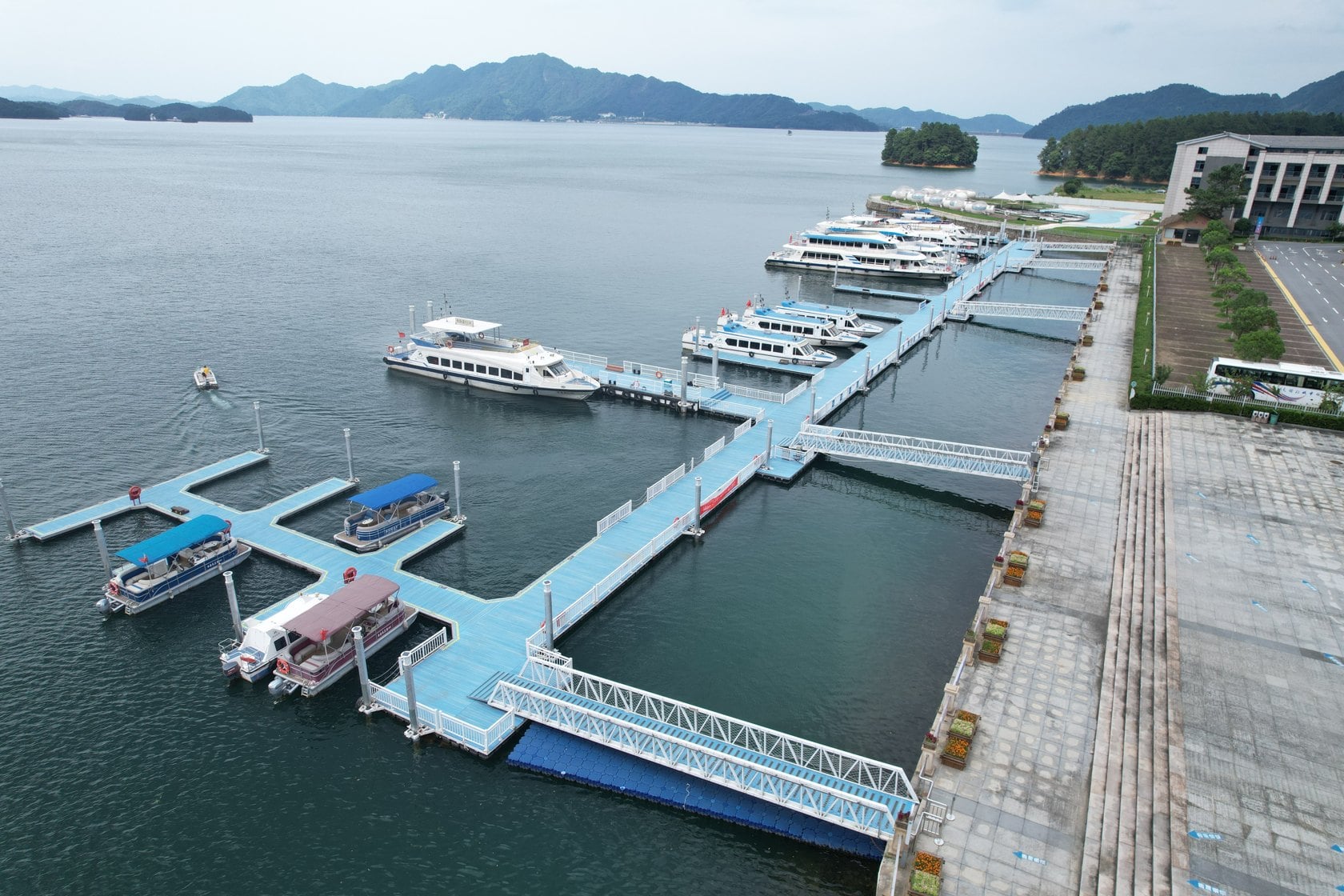
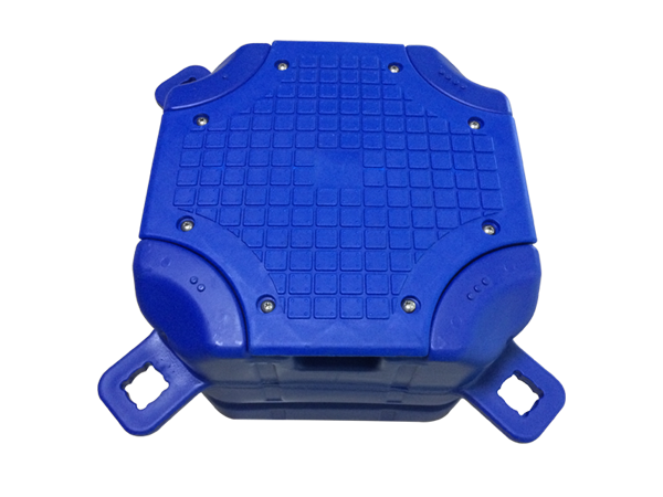
Beam spacing alone can hide a problem. In the example below, panels meeting over a beam on a 500 mm grid have just 27 mm of bearing each. The example follows a 10 m × 2 m freshwater service walkway used by maintenance staff with a small cart. The dimensions and loads are illustrative. The Hisea Dock photos show visible construction details from several installations.
What to measure on the existing dock
Record the overall length and width, the clear walking width and where the gangway bears on the floating end. If there is a frame, measure the beam center spacing, the usable width of the top bearing surface and the level difference at deck joints. Photograph the joints, the shore transition and the float-to-frame interfaces with a tape measure in view. Note which permanent fittings and temporary loads were aboard when you recorded the waterline.
Identify the float model and obtain its installation drawing. Ask which surfaces can take bearing pressure, which attachment points are available and how a float can be replaced once the deck is in place. On older platforms, look for original drawings and record the actual layout before specifying brackets.
Measure clear span and bearing at the panel joint
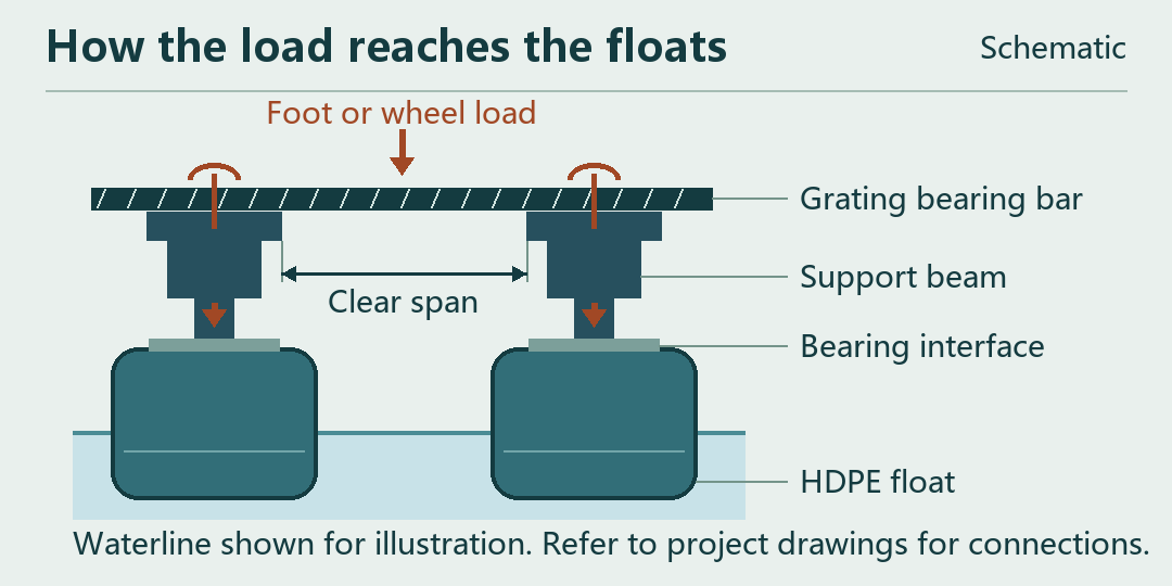
On steel bar grating, run the load-bearing bars from one support beam to the next. Dimension the center spacing, clear span and actual bearing at each panel end. Two equal 60 mm support surfaces spaced 500 mm on center leave a 440 mm clear span. Where two panels share a beam and the 6 mm joint is centered, each panel has 27 mm of nominal bearing, calculated as (60 − 6) ÷ 2.
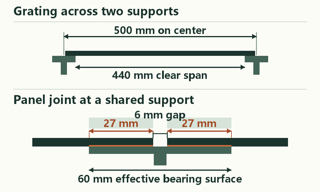
If the selected grating requires 40 mm of bearing at each end, this detail needs to change. For example, a 90 mm effective bearing surface with the same center spacing and gap gives 42 mm nominal bearing per panel and a 410 mm clear span. Check fabrication and installation tolerances and have the revised support checked. Use the grating manufacturer’s load and deflection data for the actual span and wheel footprint. For fiberglass reinforced plastic (FRP) grating, verify the bearing direction and support conditions for the chosen molded or pultruded panel.
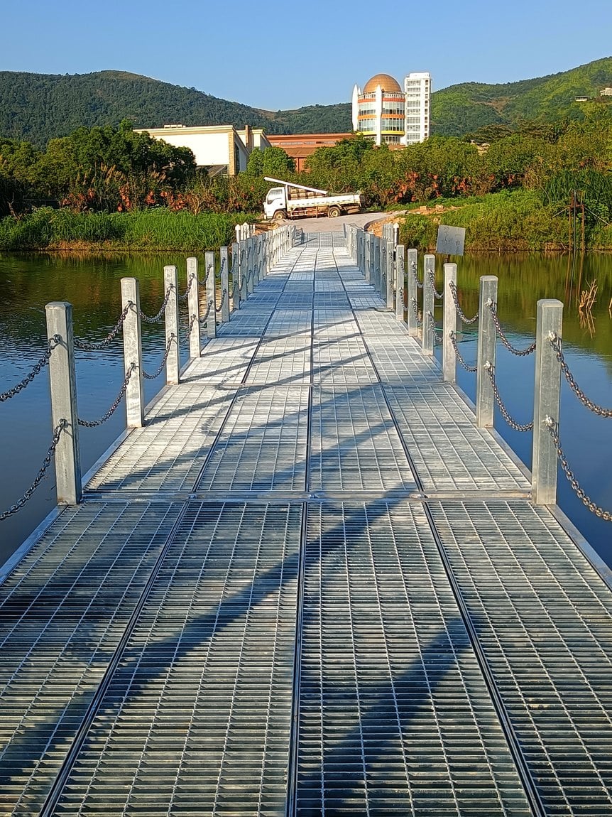
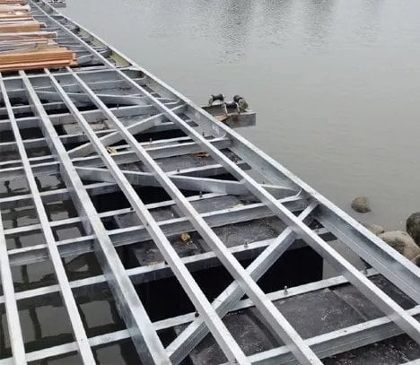
Detail both connections before ordering
Grating to beam. Identify the hold-down clip, fastener and access for removal. Show separate details for narrow edge panels, inspection openings and the gangway landing. Where a cutout interrupts a bearing bar, show how the cut bar is supported. Verify resistance to uplift and sliding for the actual installation.
Frame to float. Show where the frame bears on the floats and which brackets transfer lateral and uplift forces. Use attachment points approved for the exact float model and obtain approval before drilling a sealed float. Where floating sections can move relative to one another, detail the deck joint or transition to accommodate that movement and leave access to the connection hardware.
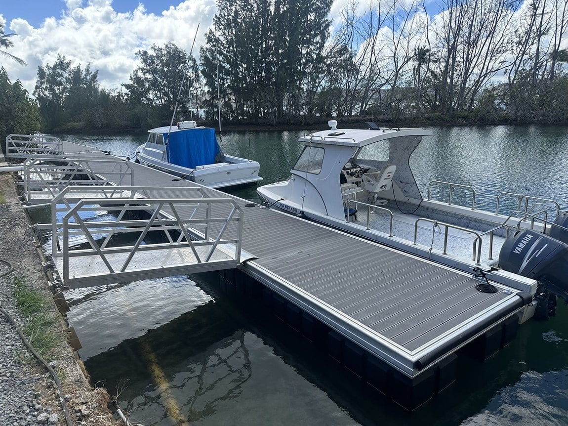
Recalculate payload and freeboard with the deck in place
In this example, the flotation data for the assembled dock give 3.60 m³ of displacement at a specified minimum clearance from the waterline to the top of the floats. In freshwater at approximately 1,000 kg/m³, that corresponds to a total supported mass of about 3,600 kg. Use displacement at the specified limit and confirm whether the manufacturer’s data include the weight of the floats.
| Item | Example value |
|---|---|
| Total mass at the specified draft | 3.60 m³ × 1,000 kg/m³ ≈ 3,600 kg |
| Existing permanent mass | Floats, existing frame, railings and fixed fittings, 1,100 kg |
| Added grating, beams and fittings | 20 m² × 25 kg/m² + 160 kg + 40 kg = 700 kg |
| Remaining uniformly distributed flotation allowance | 3,600 − 1,100 − 700 = 1,800 kg, equivalent to 90 kg/m² over the full deck |
Enter the cart as a separate load case. Supply the maximum loaded mass, axle spacing, track width and wheel contact dimensions. A wheel at midspan can govern the panel or beam. A loaded cart near the edge can govern heel and waterline clearance on the low side. Include the reaction from the gangway if it bears on the floating dock. The allowable working load depends on the structural and flotation checks for the actual assembly and site.
Measure from the waterline to both the walking surface and the top of the floats. A thicker deck can raise the walking surface while added mass makes the floats sit deeper. The two measurements show how the retrofit changes the step at the gangway and the remaining flotation reserve.
What a grating retrofit quote should include
If only the inspection hatch or gangway landing needs a removable or draining surface, price a localized retrofit. For a full deck, compare steel and FRP using the same clear span, deflection limit, wheel load and wet-surface requirements. Include the frame and hardware in the mass comparison.
- Send the site information. Include overall dimensions, float model, interface photos, proposed deck area, gangway level, water depth, design water levels and anticipated traffic.
- Request a panel plan and two connection details. Show supports, bearing direction, panel numbers and joints. Ask for separate details of the grating-to-frame and frame-to-float connections, including how to remove an inspection panel.
- Request the mass schedule and load cases. Ask for permanent mass before and after the work, allowable loads, freeboard, low-side waterline and assumptions for each relevant condition. Use the drawings to check panel IDs, bearing, fasteners and transitions on site, then verify the installed dock’s flotation against the project requirements.
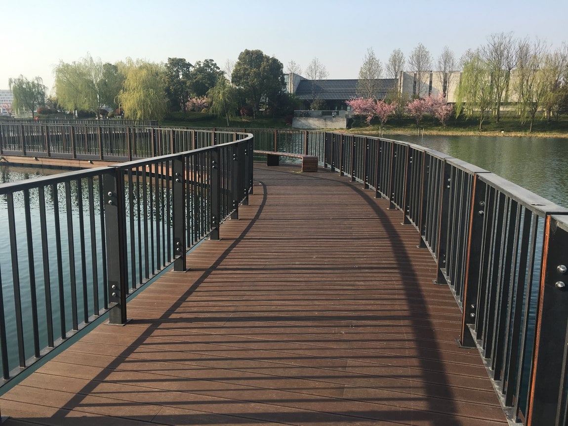
If you are modifying a floating walkway, send Hisea Dock the dimensions and photos of the landing, panel joints, float interfaces and current waterline. Contact Hisea Dock.
Technical references include Grating Pacific panel layout and installation, Fibergrate design and load tables, and the WBDG reference on floating dock freeboard and stability.

 English
 Thai
 Spanish
 French
 German
 Dutch
 Italian
 Arabic
 Indonesian
 Portuguese
 Turkish