
A modular floating dock can be installed in a lined pond. Plot the liner, the dock’s full movement envelope and the possible mooring line paths on the same drawings. Then check clearance at the lowest operating water level. Together, those checks help determine where to anchor the dock, which areas to keep clear and when to close or remove it.
Draw three boundaries on the site plan
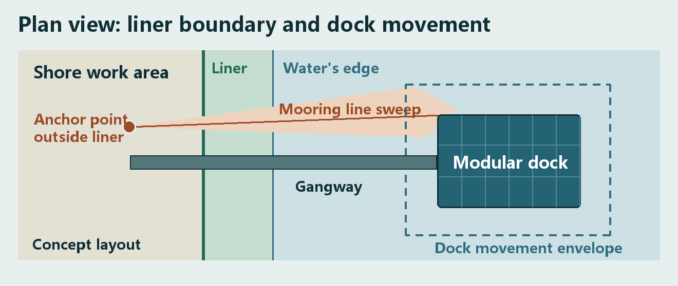
Show the liner extent, the area the dock can move through, and the area the mooring hardware can sweep through. A shore anchor can sit outside the liner while the mooring line and dock extend over it. Use sections at different water levels to check whether both clear the bank and pond bed.
Start with the as-built liner drawings. Mark the bed, side slopes, crest termination and anchor trench, protective cover, pipe penetrations and inspection points. Buried liner can extend into areas that look dry. When records are incomplete, have the owner and liner specialist confirm the edge on site before placing drill holes, trenches or equipment outriggers.
Calculate clearance at the lowest operating water level
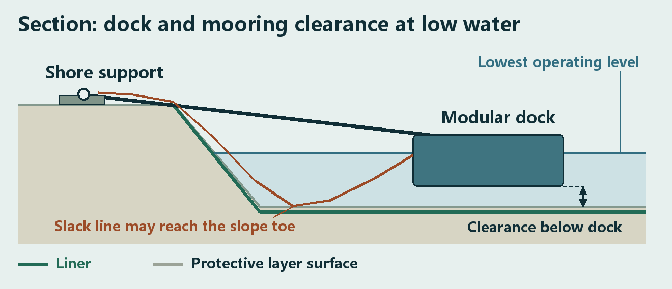
Use a common elevation datum. Subtract the elevation of the highest underwater surface anywhere in the dock’s movement envelope from the lowest operating water level. Include the finished protective cover, the slope toe and raised fixtures. From the resulting water depth, subtract the loaded static depth of the lowest component and any remaining allowance for movement and survey uncertainty.
Example: 0.62 m − 0.36 m − 0.12 m = 0.14 m
The figures are, in order, local water depth at the lowest operating level, submerged depth of the lowest component under static load, and an illustrative allowance. The remaining 0.14 m is the result for this example. The project designer determines the required clearance.
A chain, shackle or projecting fastener can touch the bed while the dock is still afloat. Check where uneven loading or a gangway reaction may lower one side of the dock. Set separate thresholds for continued use and for moving or removing the dock before a maintenance drawdown.
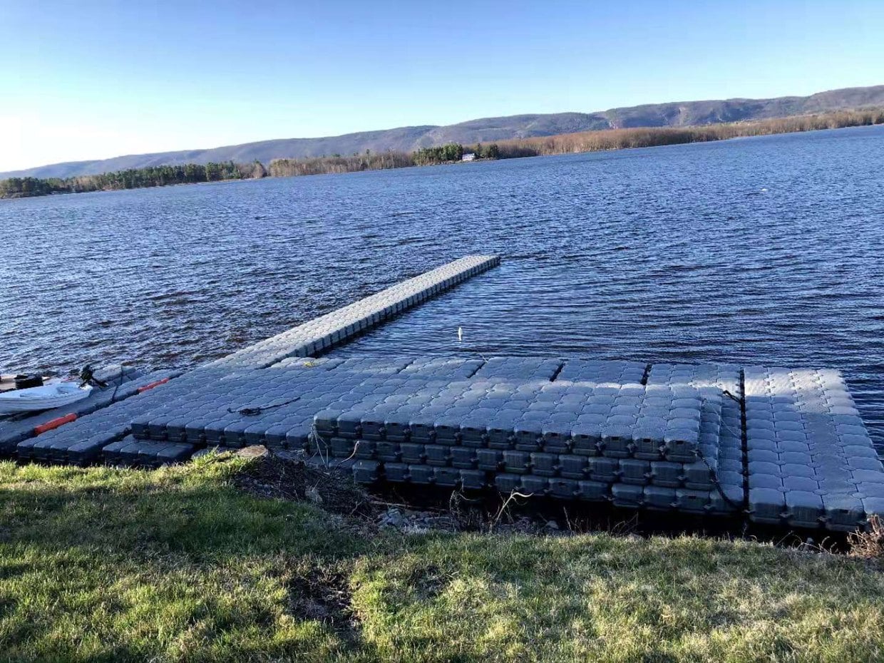
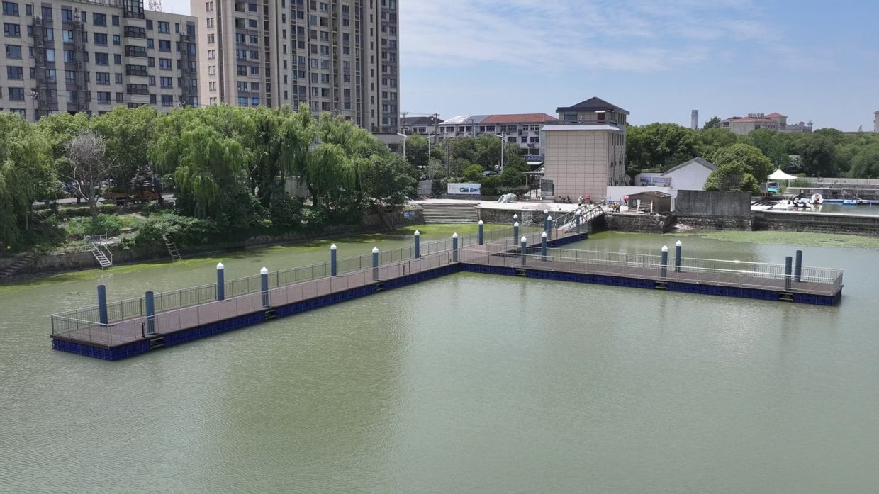
Check the mooring line even when the anchor is outside the liner
Overlay the line profiles at high and low water and at the edge of the dock’s permitted movement. Check where chains, shackles and tensioning hardware might slacken, sag or move sideways. Compare their closest approach to the bank, bed, pipe outlets and access structures.
If clearance is insufficient, compare moving the dock into deeper water, changing the shore anchor location or using a guide system. Recheck the gangway and restraint loads after changing the layout. Where contact with the protective layer is part of the design, the liner specialist should confirm bearing area, protection materials and allowable contact pressure.
| Option | What to show on the drawings |
|---|---|
| Shore anchors outside the liner | Load-bearing structure, load direction, line paths and closest approach to the liner under the governing conditions. |
| Existing guides or reserved connections | Relationship to the liner details, available travel at operating water levels, maintenance access and lateral clearance. |
| Ballast or penetrations within the lined area | Structural and liner details for bearing, movement, abrasion, sealing and inspection. |
USDA NRCS pond liner guidance · Hisea Dock’s guide to anchoring in changing water levels
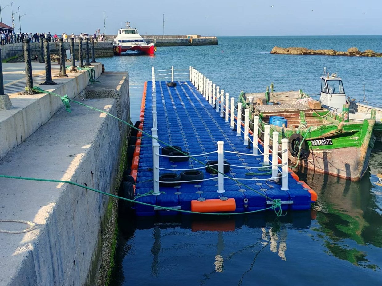
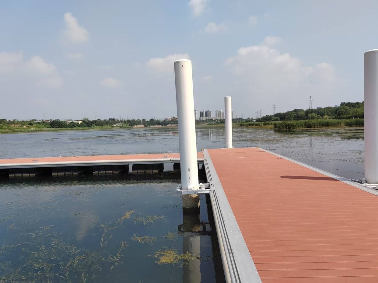
What to show at quotation, installation and handover
Show the assembly area, lifting positions, launch point and removal route on the installation plan. Identify where outriggers, temporary steelwork, tow chains and tools could touch the site. Have the liner specialist review those contact points, the proposed protective layers and the temporary loads. At handover, record the water level and the installed positions of the dock edge, gangway landing and restraint hardware.
Send to the supplier and designer
- As-built liner drawings, bank profiles, protection details and reserved connections.
- Highest and lowest operating levels, depth survey and planned drawdowns.
- Dock size and loads, access requirements and installation equipment dimensions.
Check the proposal
- Site plan showing the liner boundary, dock envelope and mooring line paths.
- Low-water section with the governing clearance and connection details.
- Installation and removal routes, plus responsibility for briefing and checking liner protection.
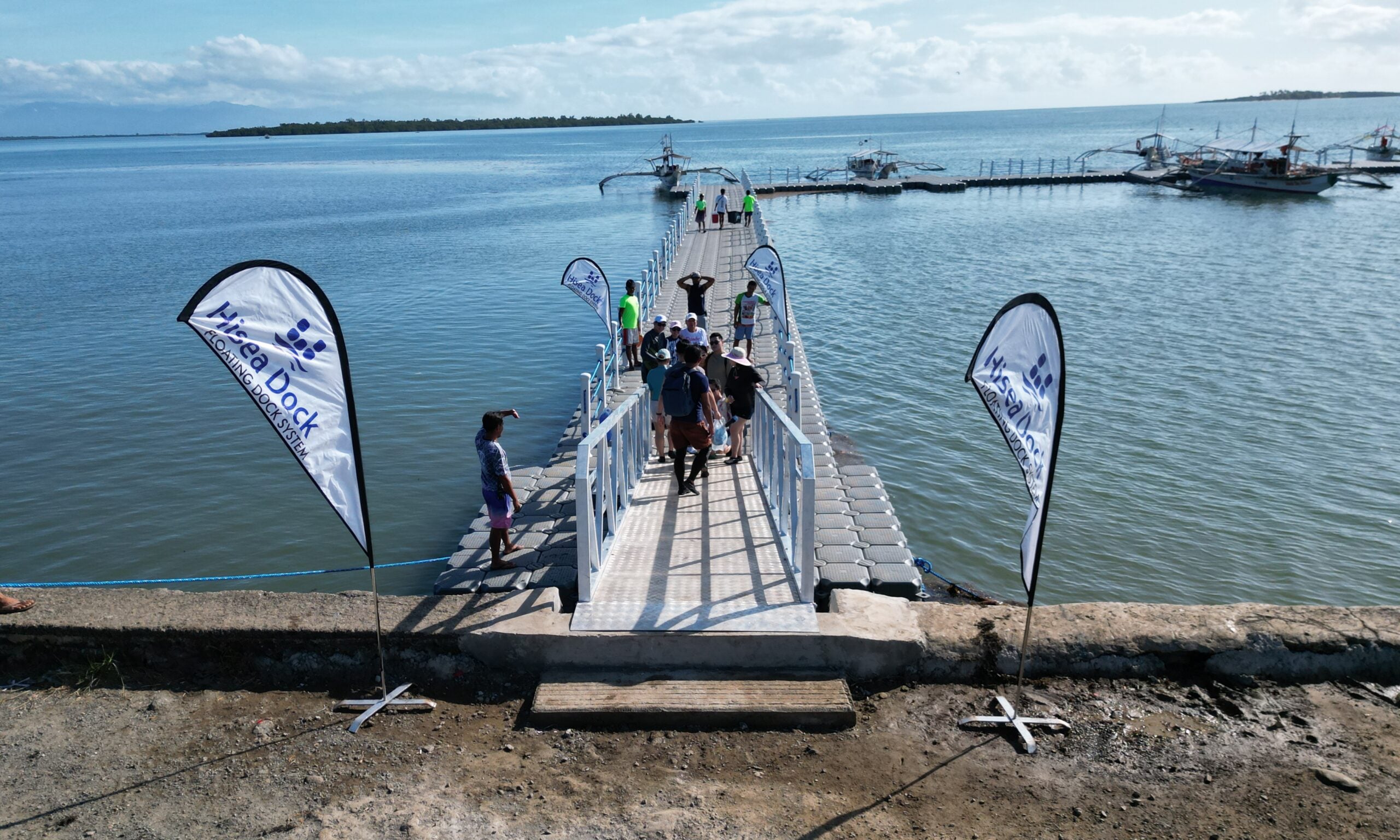
View six site survey and installation reference photos
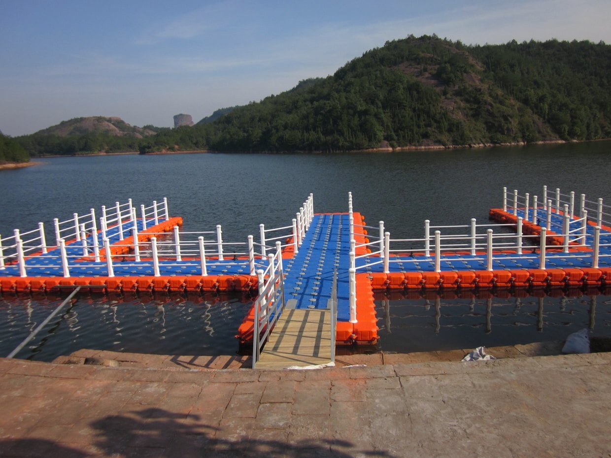
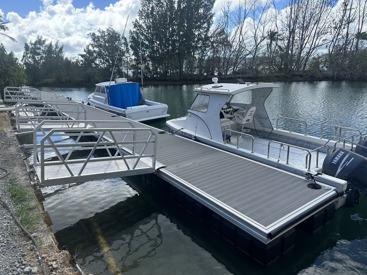
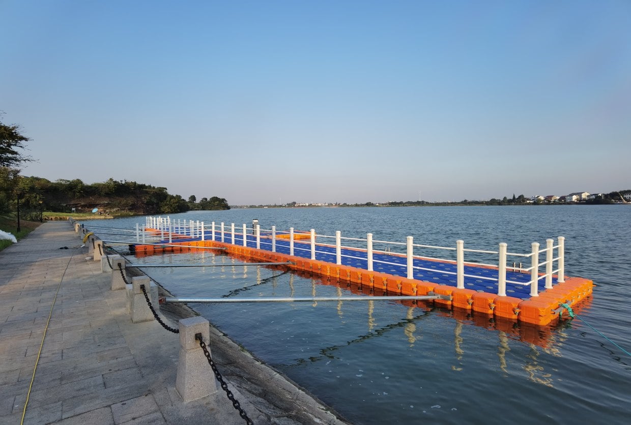
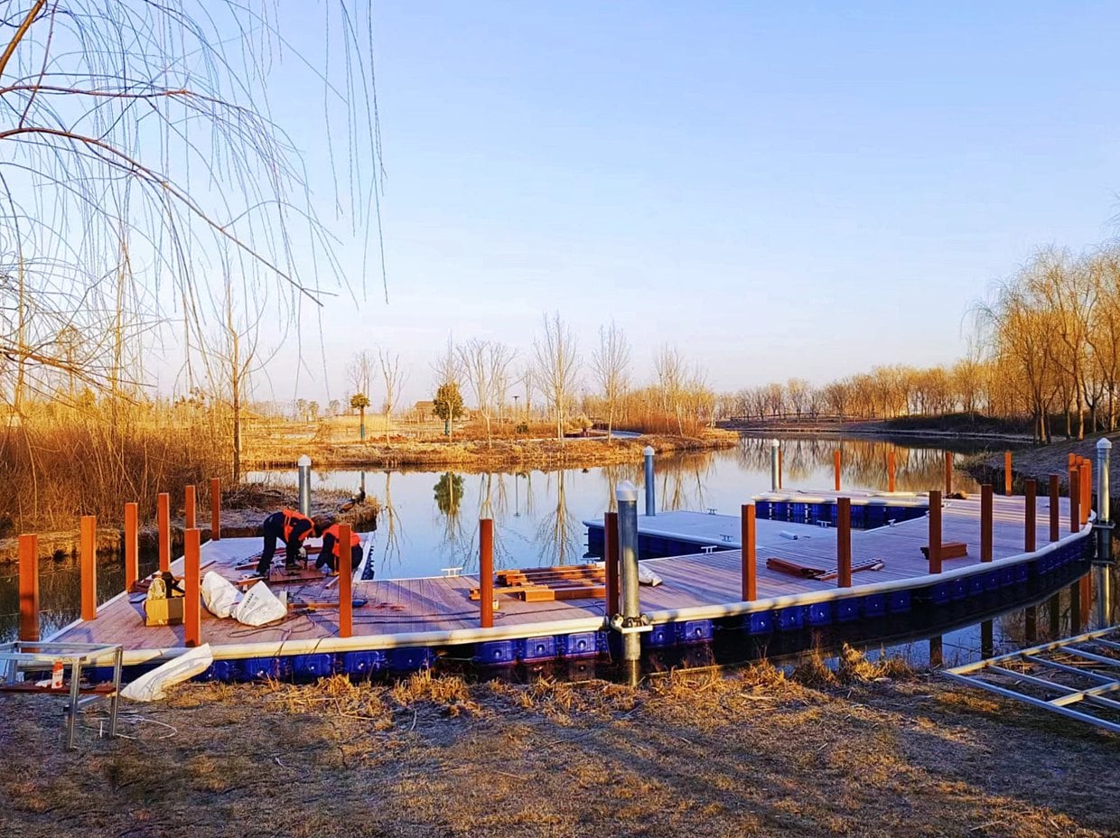
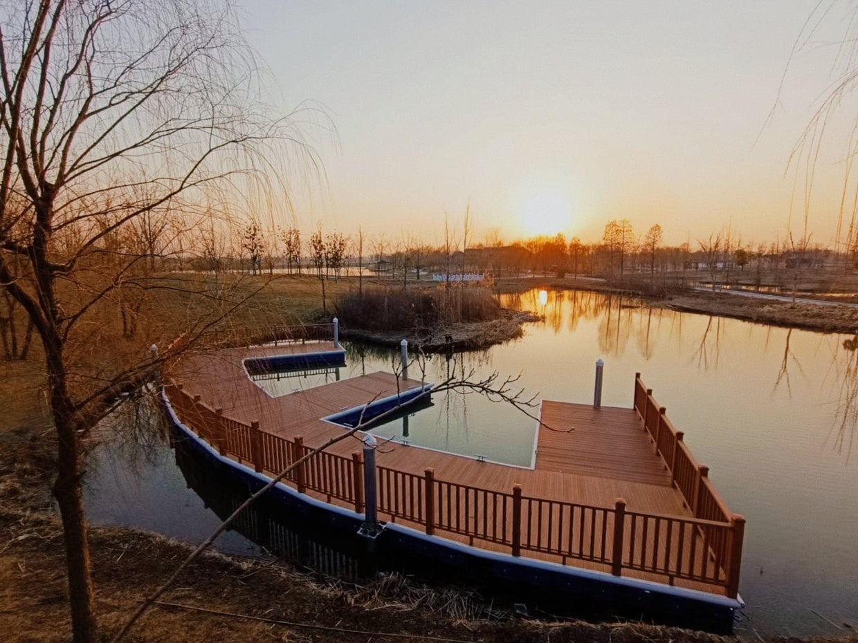
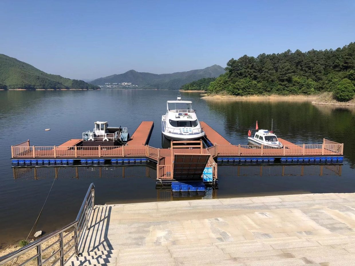
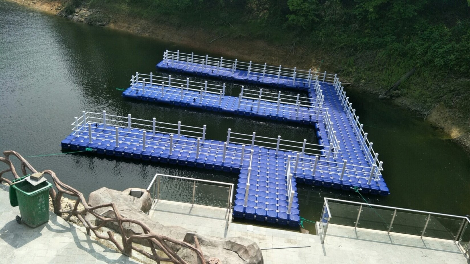
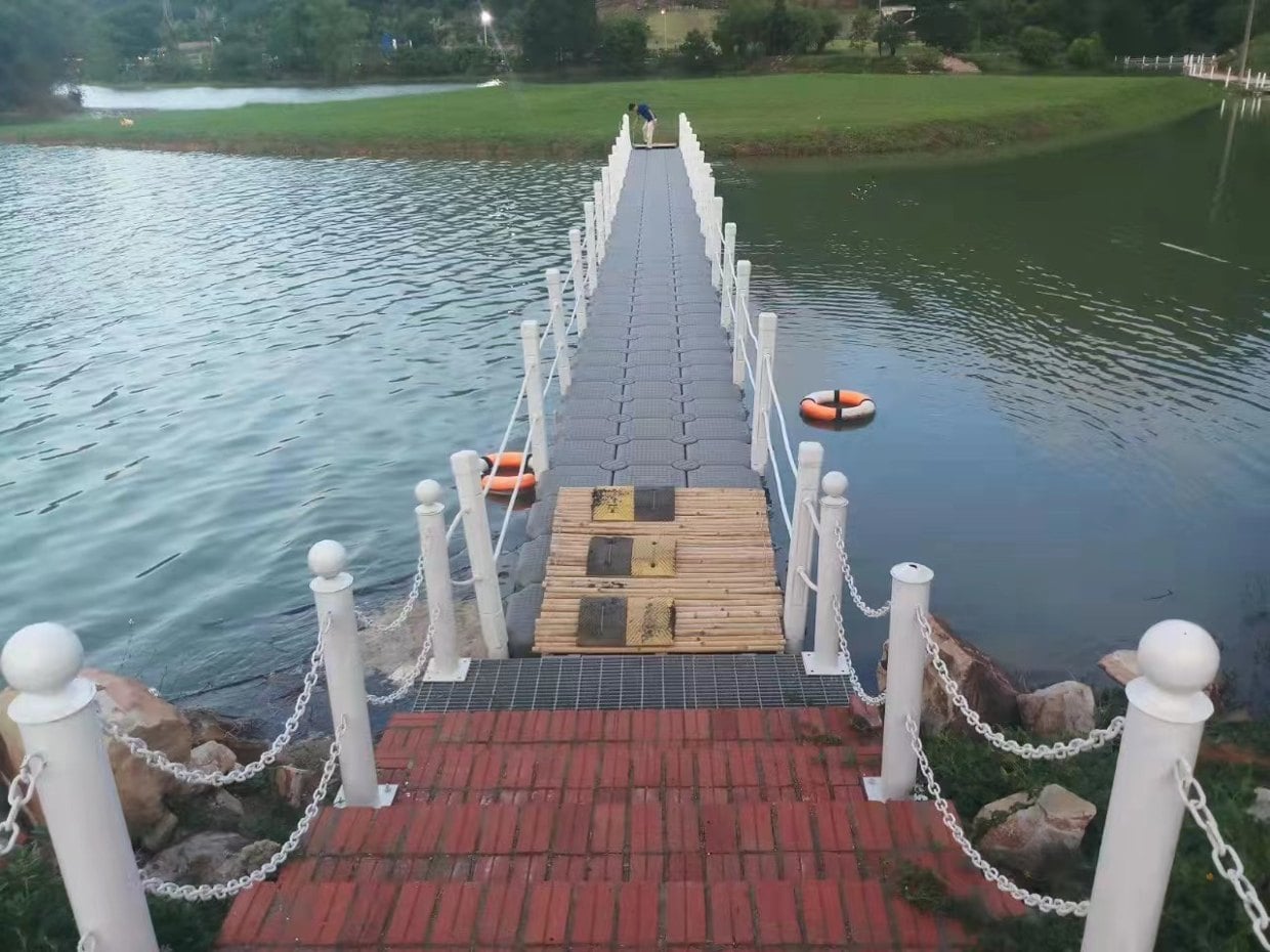
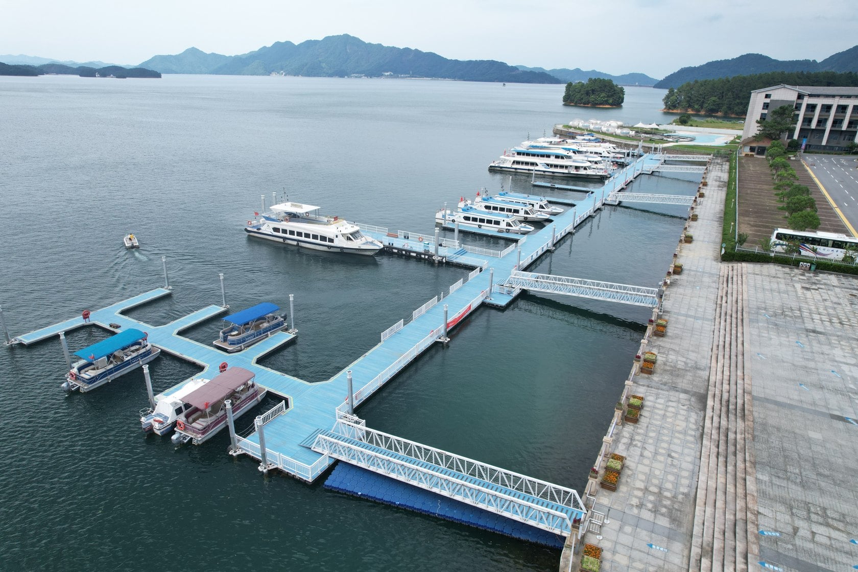
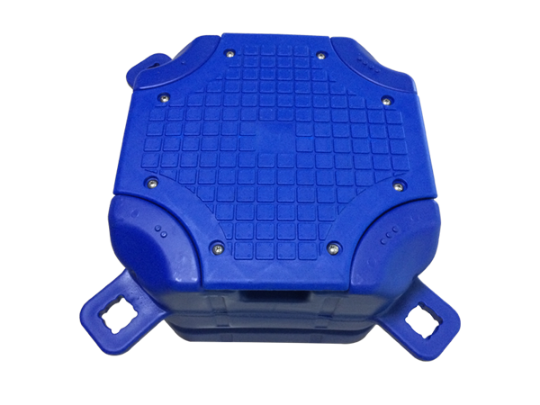
Photos are from the Hisea Dock project archive. Use the site survey and approved design for actual liner boundaries and dimensions.

 English
 Thai
 Spanish
 French
 German
 Dutch
 Italian
 Arabic
 Indonesian
 Portuguese
 Turkish