
HISEA DOCK / ILLUSTRATED TECHNICAL STUDY
The bridge needs room to rise, and restraint when the water falls. Both conditions belong in the same anchoring plan.
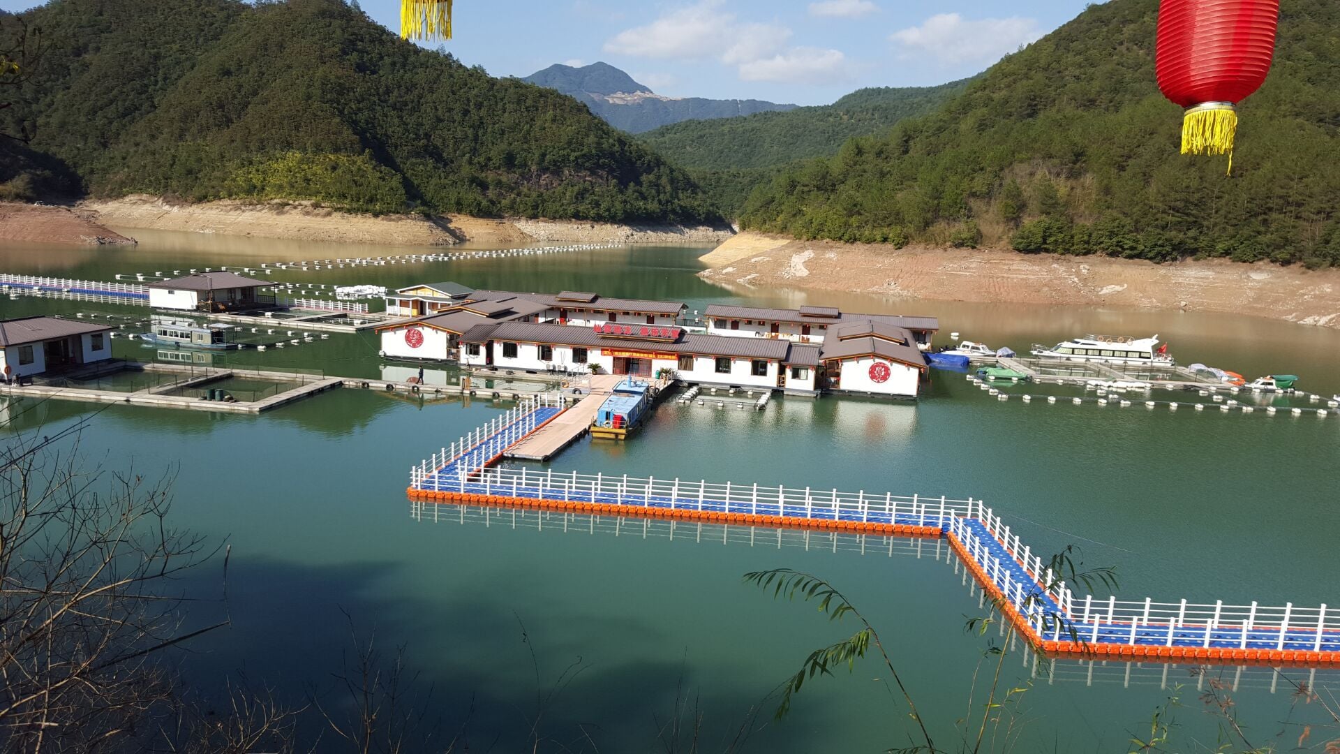
Define the water-level change first
A slow seasonal drawdown, a daily tide and a short flood are different operating conditions. Even with the same overall rise and fall, travel requirements, adjustments and maintenance can differ.
Separate the water levels at which the bridge will remain open from the extreme conditions under which it must be secured or taken out of service. A bridge that still floats may no longer provide usable shore access.
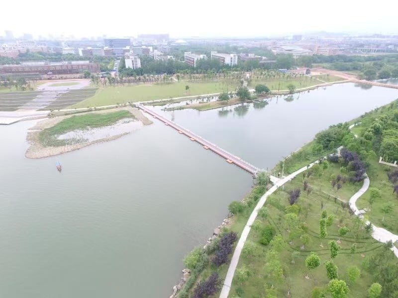
| Site information | What it affects |
|---|---|
| Water-level range and timing | Vertical travel, adjustment needs and operating limits. |
| Depth and underwater profile | Installation access, grounding at low water and movement of the shoreline. |
| Wind, waves, currents and boat wake | Load direction, repeated loading and forces at connections. A calm-weather photograph is insufficient. |
| Bed and bank conditions | How piles, anchors and shore attachments transfer loads into the ground. |
| Layout and use | Turns, long sections, canopies or berthed boats, plus navigation and maintenance space. |
Piles: restrain drift and provide travel
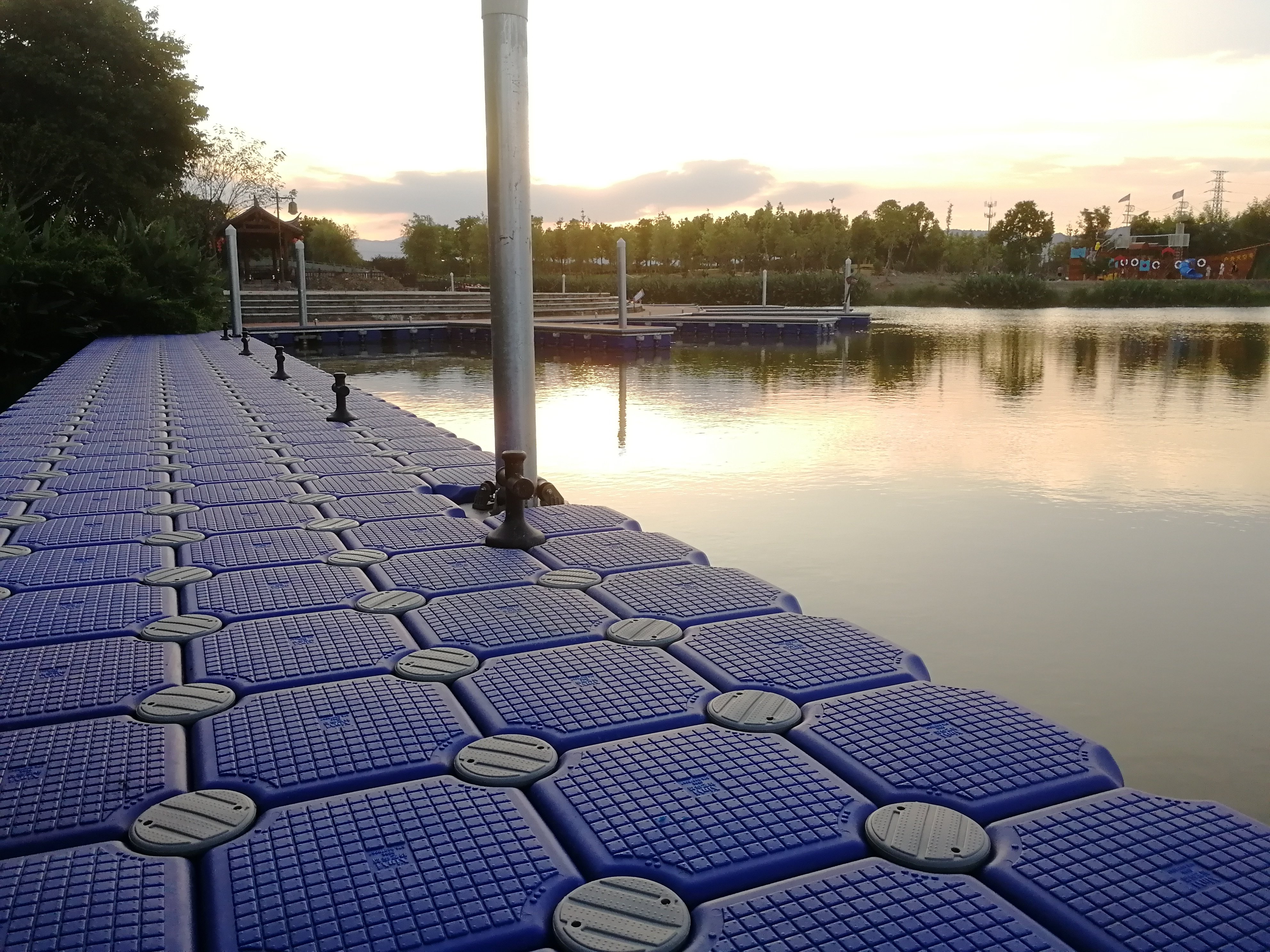
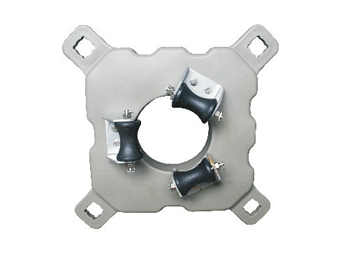
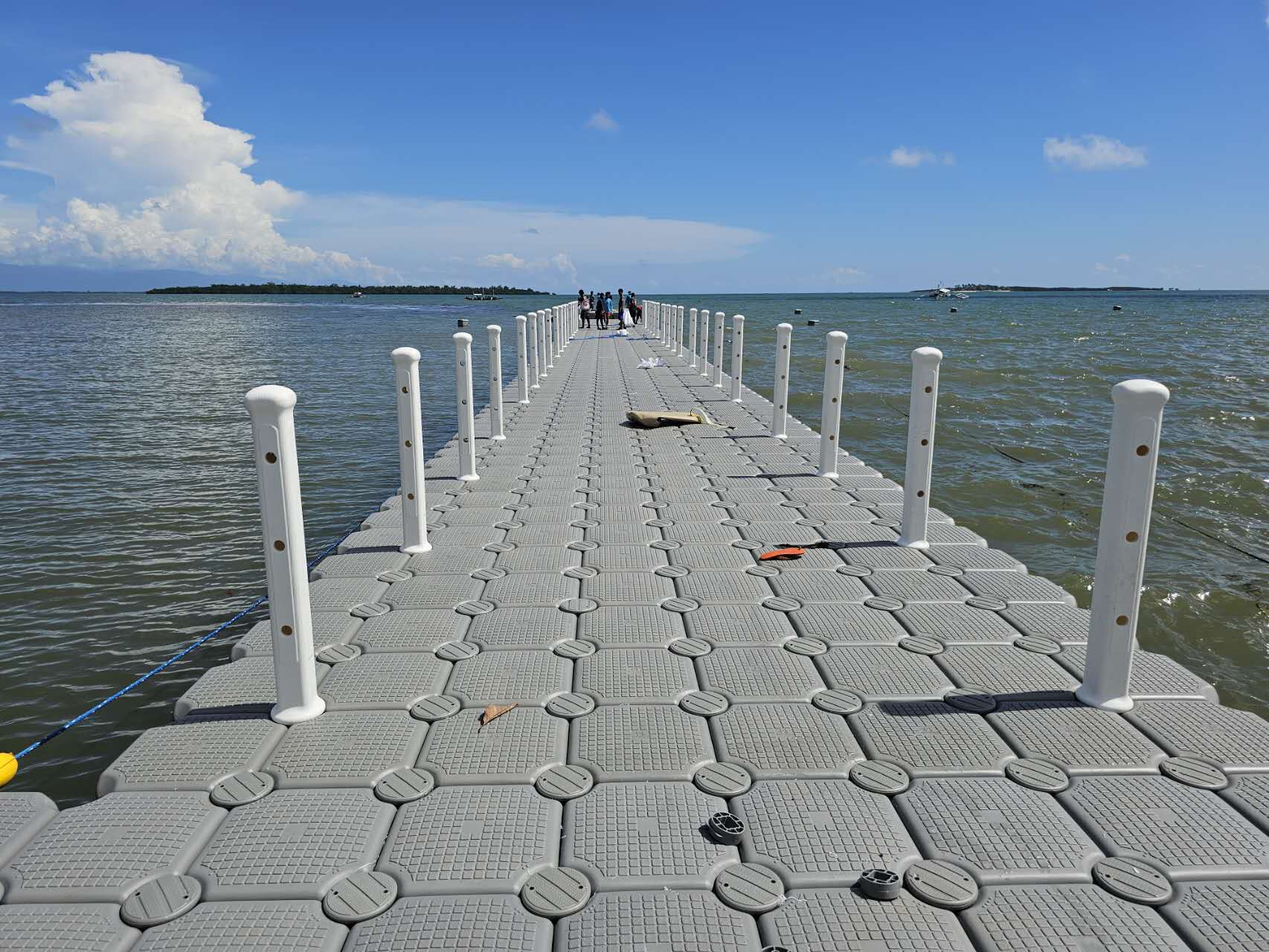
A pile and its guide can restrain horizontal movement while allowing the floating structure to move vertically. Check the whole travel range, rather than the exposed pile height on installation day. The pile-top check must include extreme high water, freeboard and water motion so that the guide cannot float off the pile.[2]
Check binding as well: a guide must accommodate the relative movement caused by deck rotation. Ground conditions, guide attachment and access to replace worn parts belong in the review.[3] Hisea Dock lists pile-guide accessories; project selection still requires confirmation of the interface and load information.[4]
Anchor lines: check the full cycle
Underwater anchors connect to the bridge through chains or cables. Changing water levels alter their geometry, tension and permitted drift. Adjustable lines or winches may suit a large range, but a fixed line with a little added slack is not a complete solution.[2]
Review bridge attachments, lines and end fittings together. An anchor’s weight in air is only one input: submerged weight, bed conditions, load direction and connection capacity also matter.
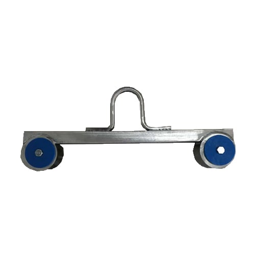
The proposal should identify where loads enter the bridge, which fittings transfer them and where they reach the ground. A component photograph cannot replace connection details and capacity information.
Give shore restraints and gangways defined roles
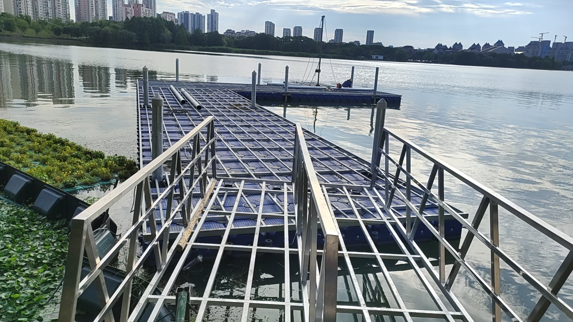
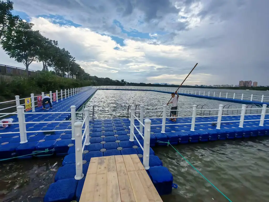
Shore restraints can help control the approach section. They need suitable ground attachments and geometry compatible with bridge movement. A handrail is not automatically an anchoring point; design the shore cables and approach connections together.[1]
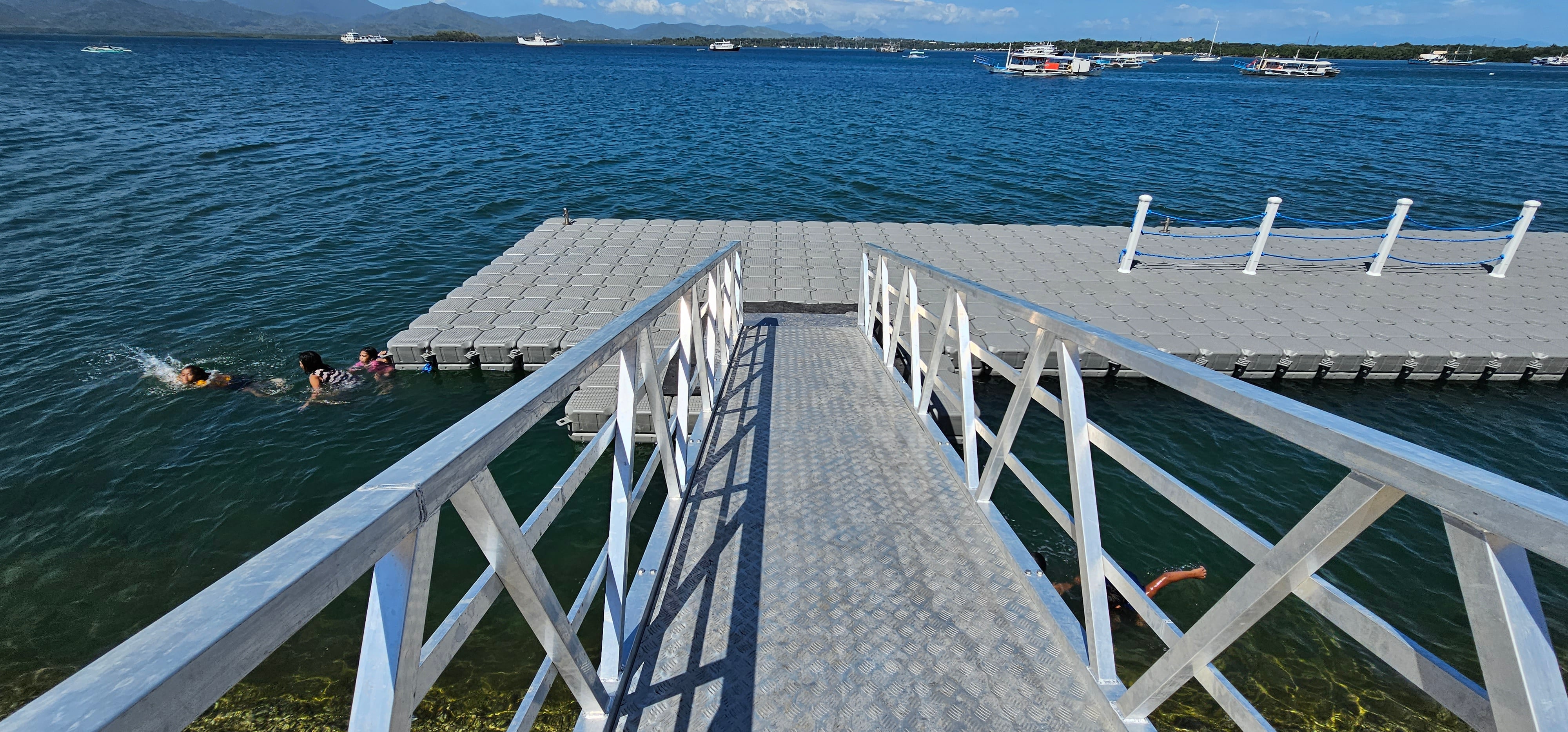
A gangway provides access. As water levels change, its slope and horizontal projection change. Shore hinges with sliding or rolling support at the floating end are common arrangements; check movement, bearing overlap and retention for the actual structure. Hinges alone may not accommodate longitudinal displacement.[2]
Any positioning role assigned to the gangway must be explicit. Its support reactions must also be included in the flotation assessment, rather than estimated by simply spreading its weight across the bridge.
Review three conditions on one drawing
Ask the supplier and designer to overlay the bridge, restraints and gangway at different water levels. This makes incompatible movement easier to spot than a single normal-water rendering.
| Condition | Questions to resolve |
|---|---|
| Design low water | Could the approach ground? Do lines retain the required restraint? Are gangway slope, overlap and access acceptable? |
| Design high water | Are guides within their travel? Do lines obstruct rising flotation? Could gangway ends bind, disengage or leave hazardous gaps? |
| Extreme event | Address site-relevant flooding, waves, debris or ice, and define closure, inspection and securing or removal arrangements. Continued public access is not assumed. |
Translate the review into practical inspection requirements: guide wear, loose connections, line abrasion and bank scour. Inspection locations and adjustment methods need to be accessible on site.[1][3]
Questions buyers ask
Does a large water-level range always require piles?
No. Compare ground conditions, available travel, installation access and position-control needs. Engineered anchor-line systems are another option. Site information must come before a final selection.
Will heavier anchors and tighter lines make the bridge more stable?
Not necessarily. The ground, lines and bridge attachments work together. Excessive restraint can obstruct vertical movement; adjustment should follow the design and inspection requirements.
What should I send a floating bridge manufacturer?
Start with the location, intended use, proposed dimensions, overview and shore photographs, and water-level records. Identify missing depth or ground information so that survey and design responsibilities can be agreed.
Bring the site information to Hisea Dock
For a floating bridge or platform enquiry, send site photographs, water-level information and preliminary dimensions. Include daily use, berthing needs and installation timing. Confirm the supply scope for floats, connectors, restraints and installation guidance in the quotation.
www.hiseadock.com
WhatsApp: +86 17369861101
Technical references
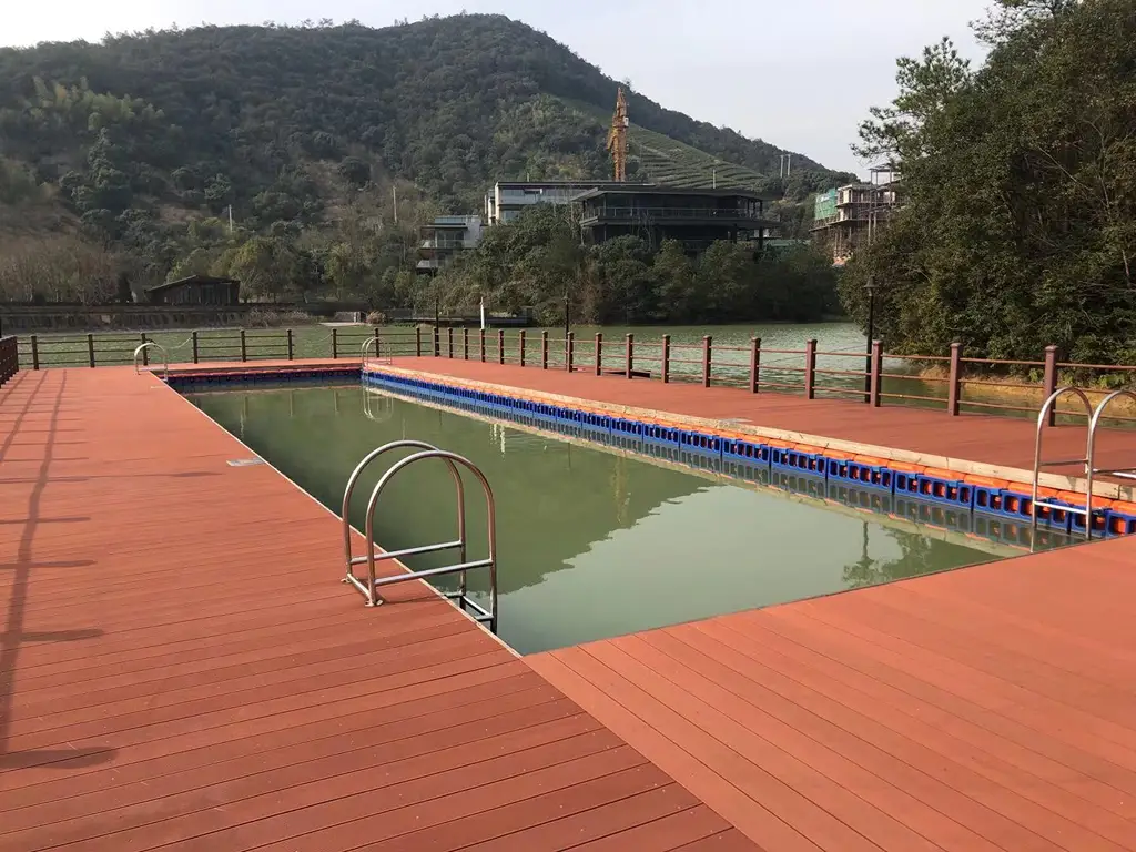
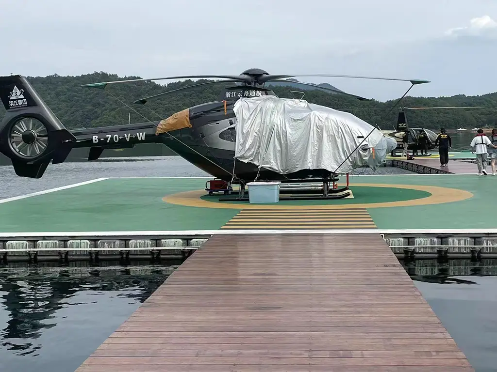
These publications explain anchorage, load transfer and movement principles. UFC addresses small-craft berthing; the TMR manual addresses recreational boat-launching facilities. References are not product certifications or a substitute for local project requirements. Photographs were supplied by the company; hidden construction, design water levels and capacities have not been inferred from them.
- USDA Forest Service · Floating Trail Bridges and Docks (2002), printed pp. 15–21, 23–24
- UFC 4-152-07, Change 1 (2012), §§6-3.4, 6-4.2.3, 6-6.2; printed pp. 33–38, 42, 44–45
- Queensland TMR · Design Criteria for Floating Walkways and Pontoons (2015), §§4.5, 4.7, 5.1, 8.2–8.3; printed pp. 7, 9–10, 14–15
- Hisea Dock · Pile Guide

 English
 Thai
 Spanish
 French
 German
 Dutch
 Italian
 Arabic
 Indonesian
 Portuguese
 Turkish