
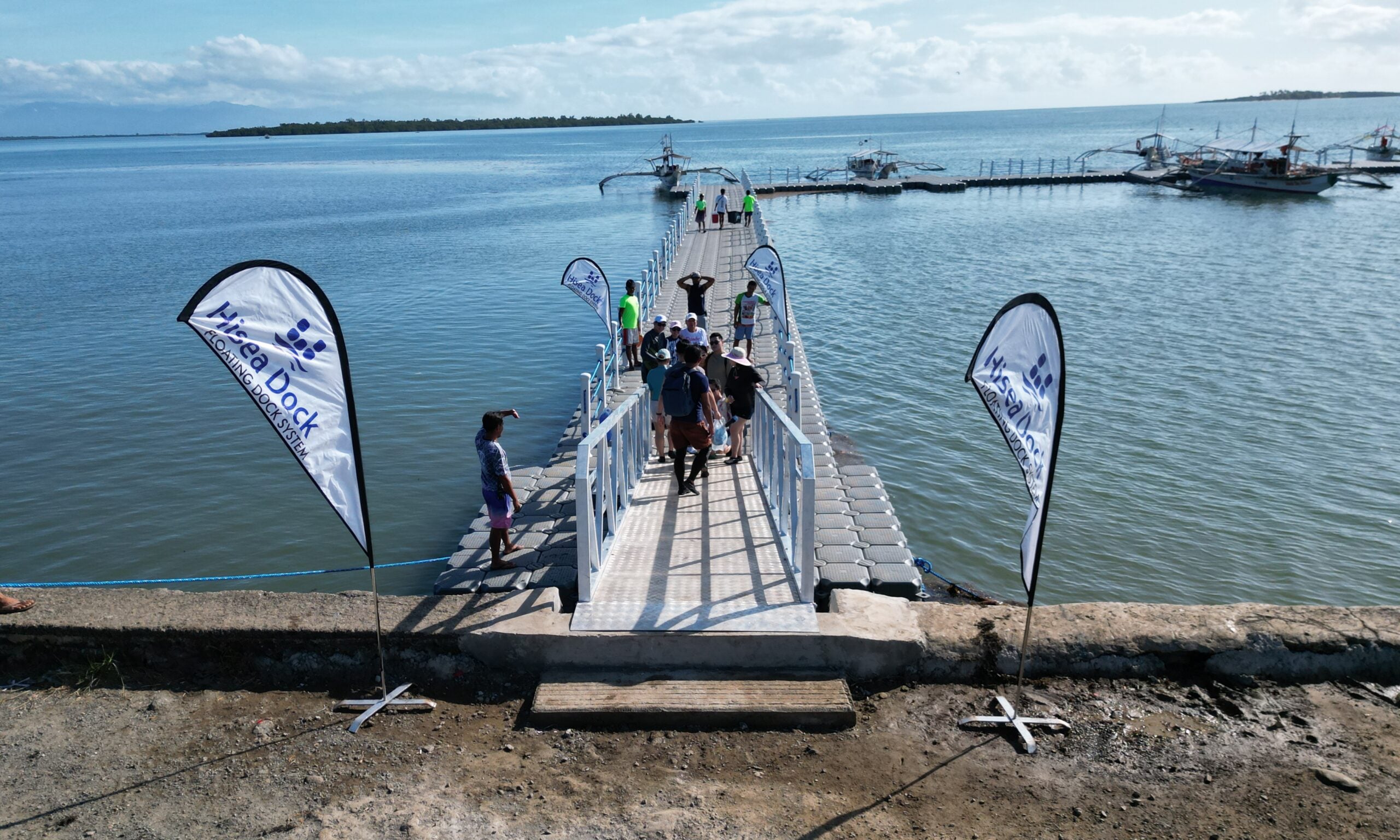
A gangway with a hinged or sliding connection is a common way to connect an existing fixed pier to a modular floating dock. Before choosing the layout, check where the existing structure can carry the gangway reaction, where the floating end will land at high and low water, and how the dock will be held in position.
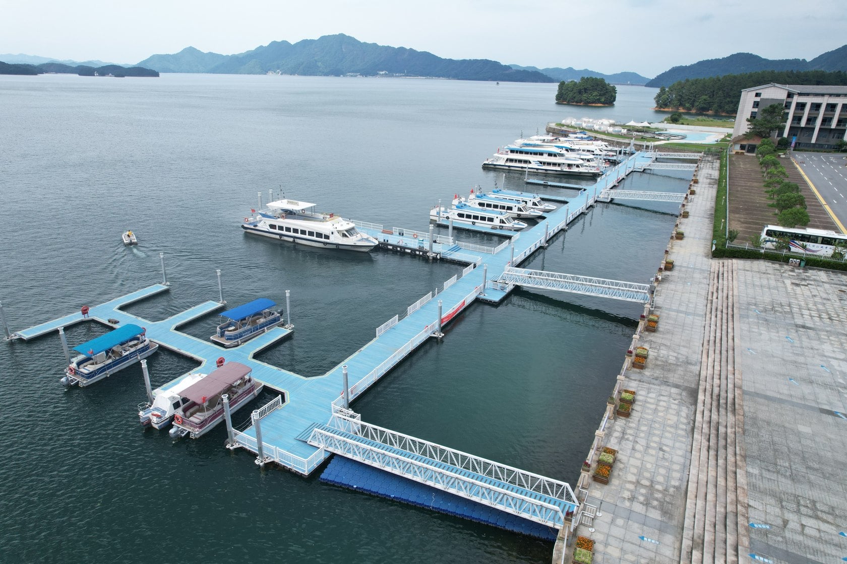
Where can the gangway land on the existing pier?
Mark the proposed opening and gangway centerline on the existing drawings. A flat concrete surface may be a structural slab, a seawall cap, or a wearing surface over another structure. Ask the project engineer to identify the member that can take the gangway reaction and check the proposed connection and the existing structure.
Use one elevation datum for the fixed landing, highest and lowest operating water levels, and any survey levels. Record the location and water level for each depth measurement. On the plan, mark steps, wall corners, protruding piles and vessel clearance so the designer can compare a straight approach with an angled one.
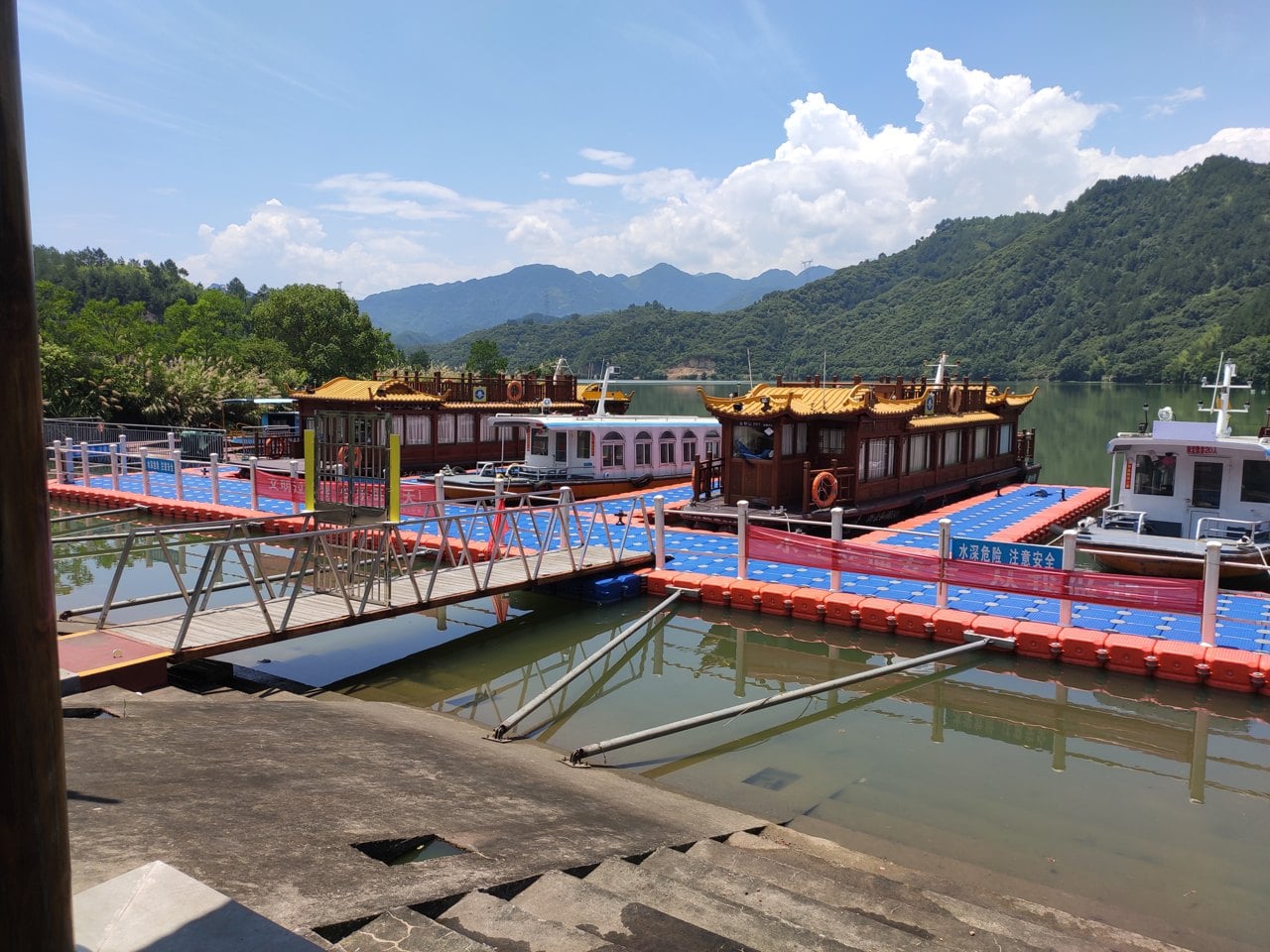
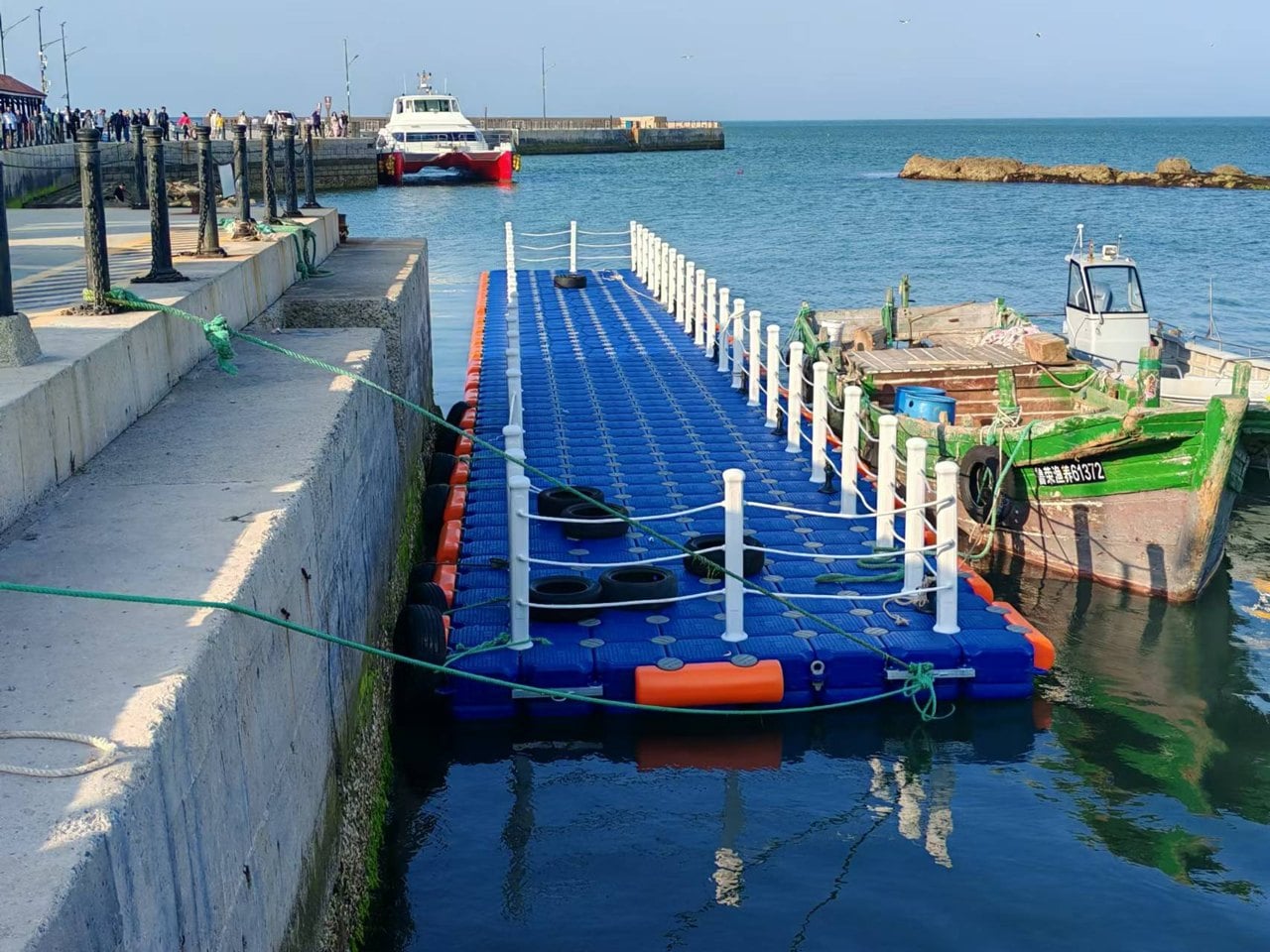
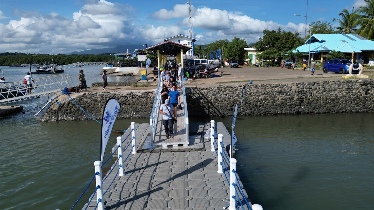
How much does the same gangway move as water levels change?
Estimate the floating deck elevation by adding loaded freeboard to the water elevation for each condition. As the gangway pivots, its horizontal run changes with its slope. Check both ends of the operating range and consider a reverse slope if the floating deck can rise above the fixed landing.
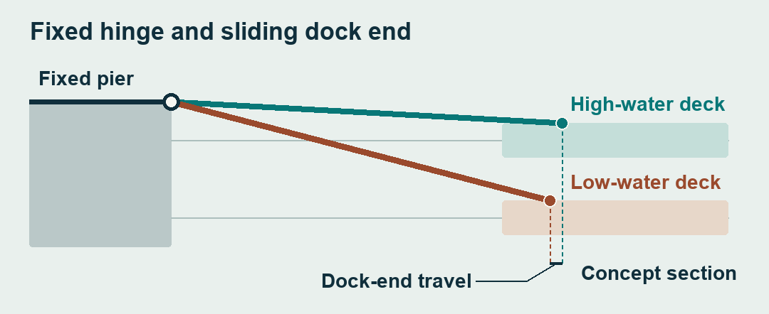
Example with a 6.00 m gangway. The distance between the supports is 6.00 m and the fixed landing is at +3.00 m. For each condition, divide the elevation difference by the corresponding horizontal run and multiply by 100 to get the slope.
| Condition | Dock deck elevation | Elevation difference | Horizontal run | Slope |
|---|---|---|---|---|
| High water | +2.75 m | 0.25 m | 5.995 m | 4.2% |
| Low water | +1.75 m | 1.25 m | 5.868 m | 21.3% |
The horizontal run changes by about 0.13 m in this example. That is the geometric change from the gangway pivoting. The project designer also needs to allow for dock movement and installation tolerances when sizing the bearing area. Check the applicable slope, transition plate and accessibility requirements for the site and its intended use.
U.S. Access Board guidance on recreational boating facilities
Leave a bearing area for the moving end
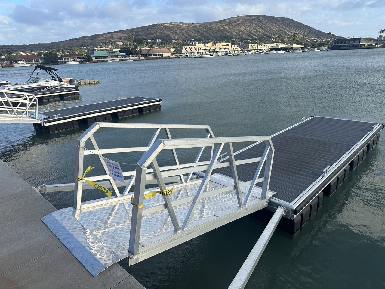
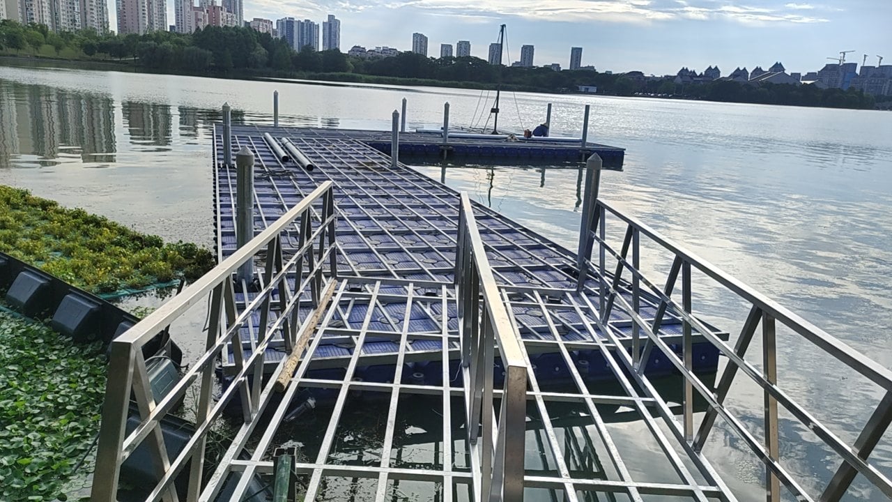
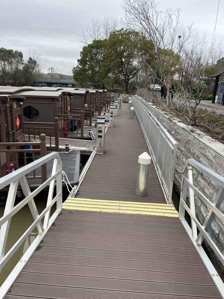
A common arrangement pairs a fixed-end hinge with rollers or sliding support at the dock end. Ask the designer to show the moving end’s full operating range. Check minimum bearing overlap, gaps and changes in level at the transition plate, and clearance from railing posts or other hardware. The gangway concentrates its reaction near the bearing area. Review the support, local freeboard and deck tilt under the design loads.
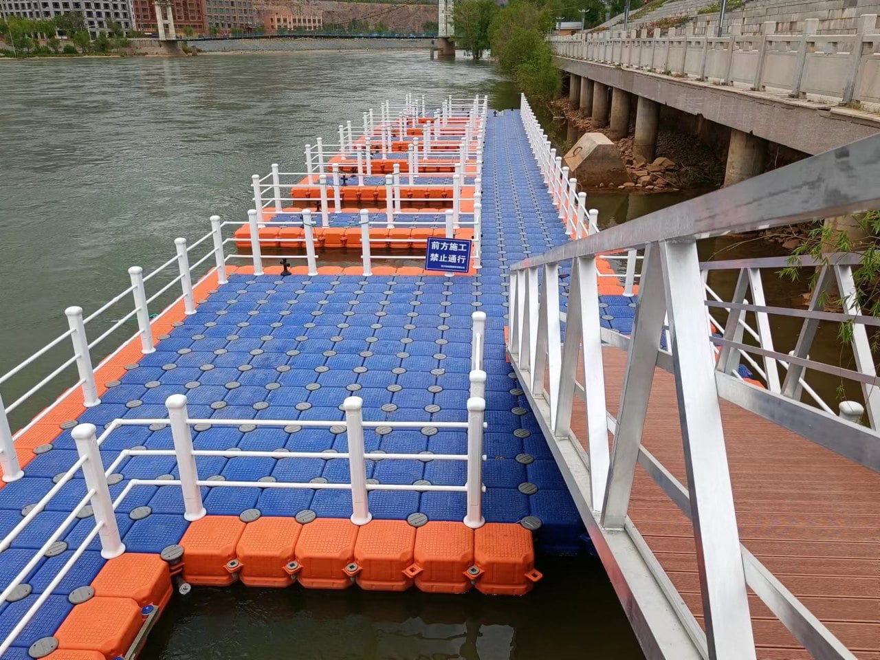
Docks, Piers and Wharves, New York Sea Grant design guide hosted by NOAA
Check dock restraint and gangway movement together
Guide piles, shore restraints and moorings are options for holding a floating dock in position. The choice depends on depth, bed conditions, the shore structure and environmental loads. For guide piles, verify working travel across the operating water levels. Along a wall, check lateral clearance, fenders and protrusions.
Overlay the possible dock positions on the gangway plan. Where currents or vessel wakes can move the dock, check whether the end support remains on its bearing surface as the dock shifts or turns. The designer should also verify any additional lateral forces at the gangway connections.
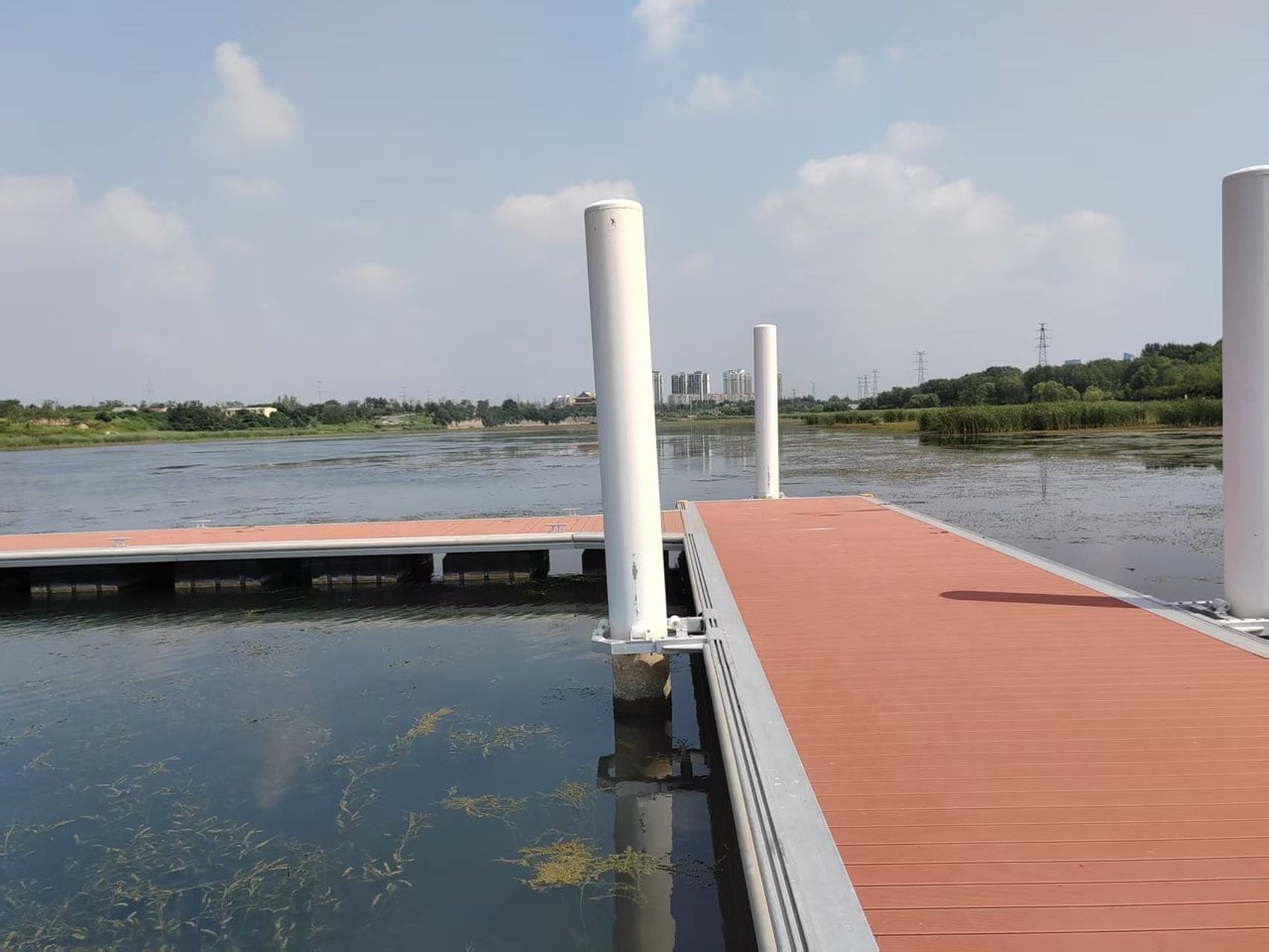
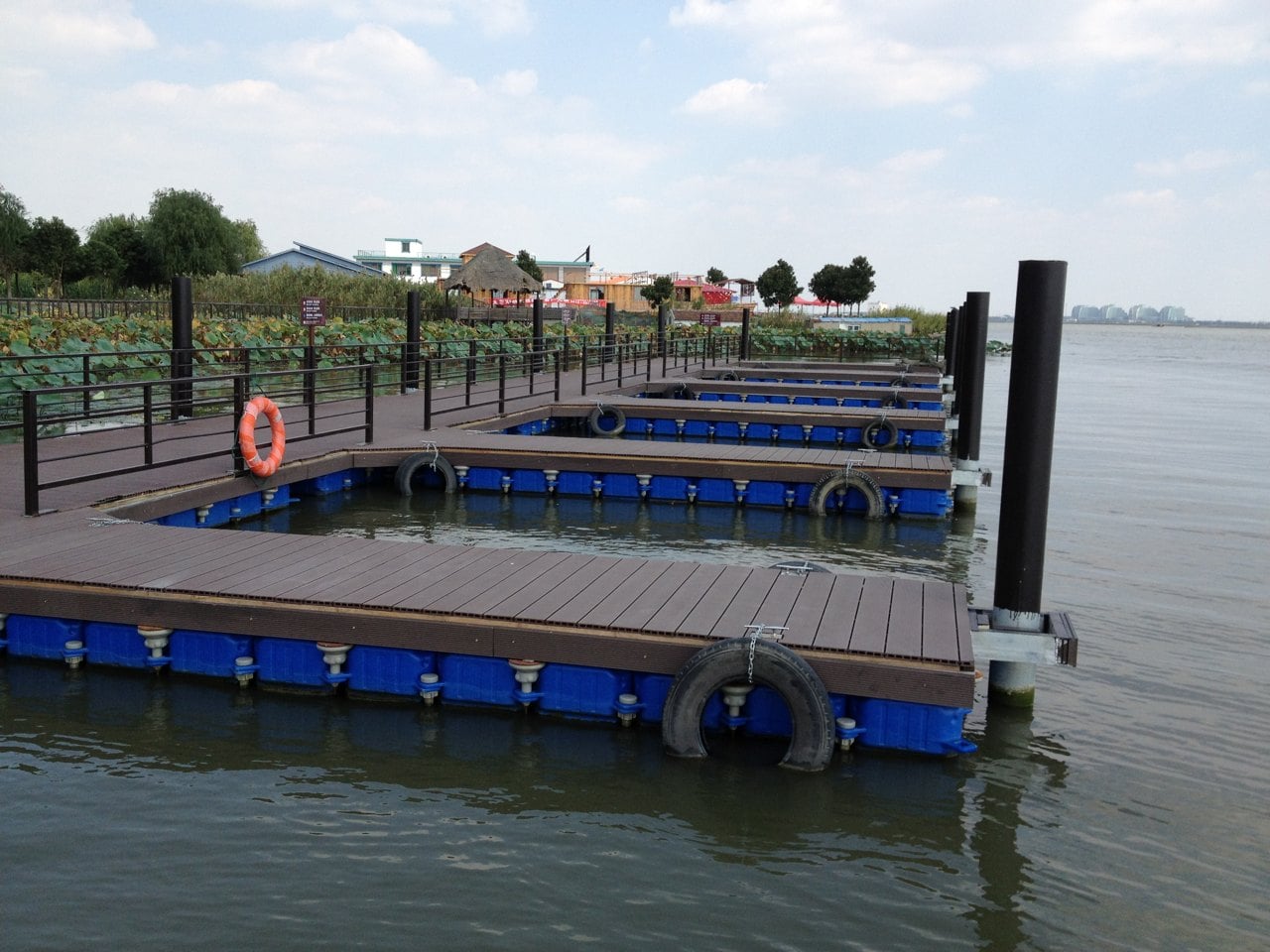
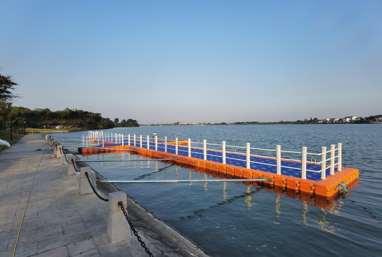
U.S. Army Corps of Engineers guide pile detail example · Hisea Dock’s guide to anchoring a floating bridge across changing water levels
What to send with a retrofit quote request
Send to the supplier and designer
- Existing pier plan, proposed connection location, close-up photos and available structural drawings.
- Fixed-end elevation, operating water levels and surveyed depths tied to the same datum.
- Clear walking width, expected traffic, cart or equipment access, accessibility requirements and construction constraints.
Check the drawings and scope
- High and low water sections showing slope and dock-end position.
- Details of the fixed connection, floating-end support and restraint.
- Supply and installation responsibilities for the gangway, mounting seat, transition plates and restraints.
To reuse an existing gangway, provide its measured length, clear width, connection details and maintenance records. Have the designer verify that it can accommodate the new support positions and range of movement.
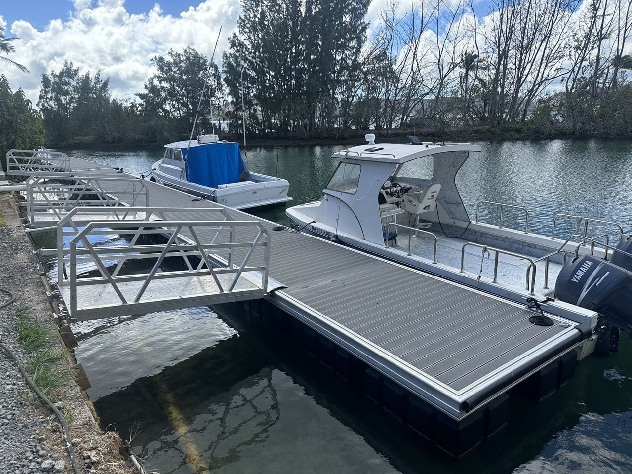
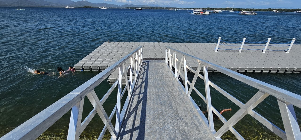
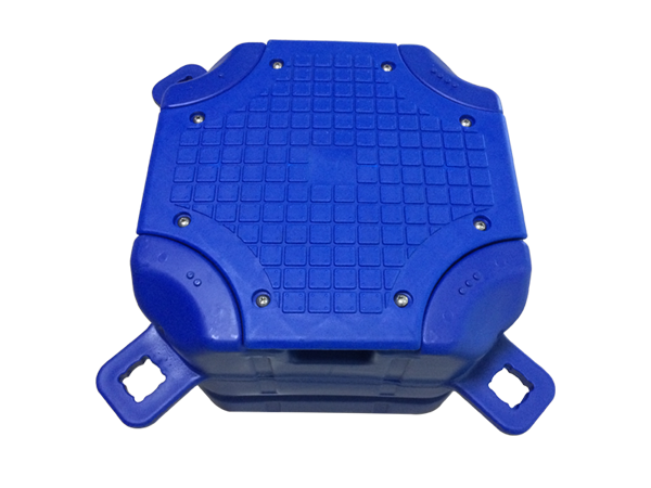
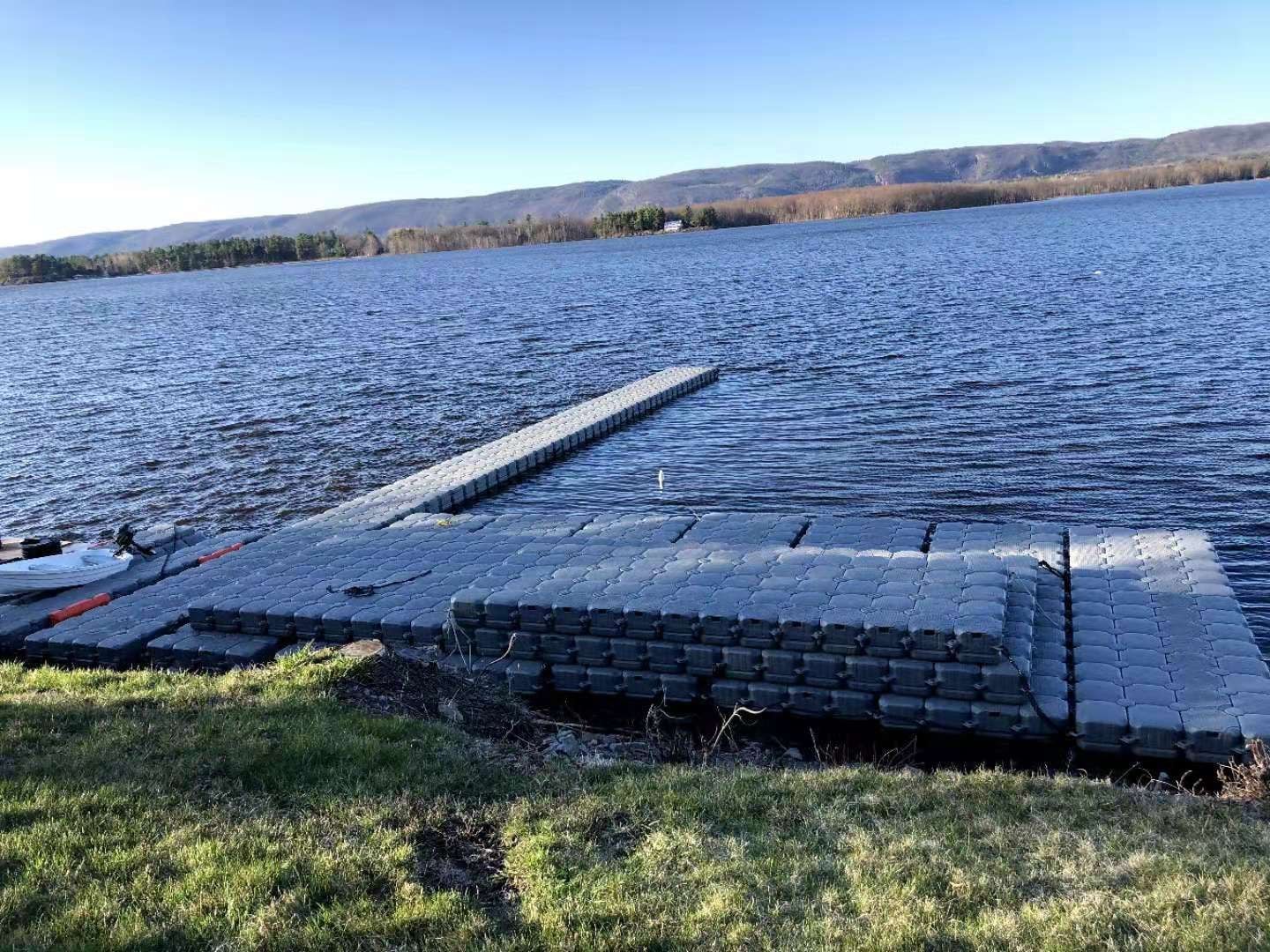
Project photographs are from the Hisea Dock case archive and include modular float and pontoon installations. The section and dimensions illustrate the calculation.

 English
 Thai
 Spanish
 French
 German
 Dutch
 Italian
 Arabic
 Indonesian
 Portuguese
 Turkish